Kirchhoff's laws
Circuit analysis is designed to find the voltage across or the current through any circuit element, and if need be the power consumed by its resistances or supplied by its sources. By far the most important aids to this analysis are Kirchhoff's two laws. They are fundamental to circuit analysis, and with them, and the current and voltage relations for circuit elements
The two laws are:
- Kirchhoff's voltage law
- Kirchhoff's current law
Kirchhoff's voltage law
The algebraic sum of the voltages at any instant around any loop in a circuit is zero.
Symbolically,
\[\sum~v= 0 \]
Kirchhoff's voltage law is a consequence of the principle of energy conservation; so frequent is its use in circuit theory that it is usually abbreviated to KVL.
Kirchhoff's current law
The algebraic sum of the currents at any instant at any node in a circuit is zero.
Symbolically,
\[\sum~i= 0 \]
KCL - its usual abbreviation - is a result of the principle of charge conservation
Illustrating Kirchhoff s laws.
The voltage law is used on loops ABCDEF A and ABEFA. The current law is used at node B.
A branch of a circuit is a path containing one circuit element. In figure AB is a branch, EF is not. A node is a point in a circuit where branches join. In figure, A and B are nodes, but F is not. There is also a node between the 4\(\Omega\) resistance and the \(4 V\) source.
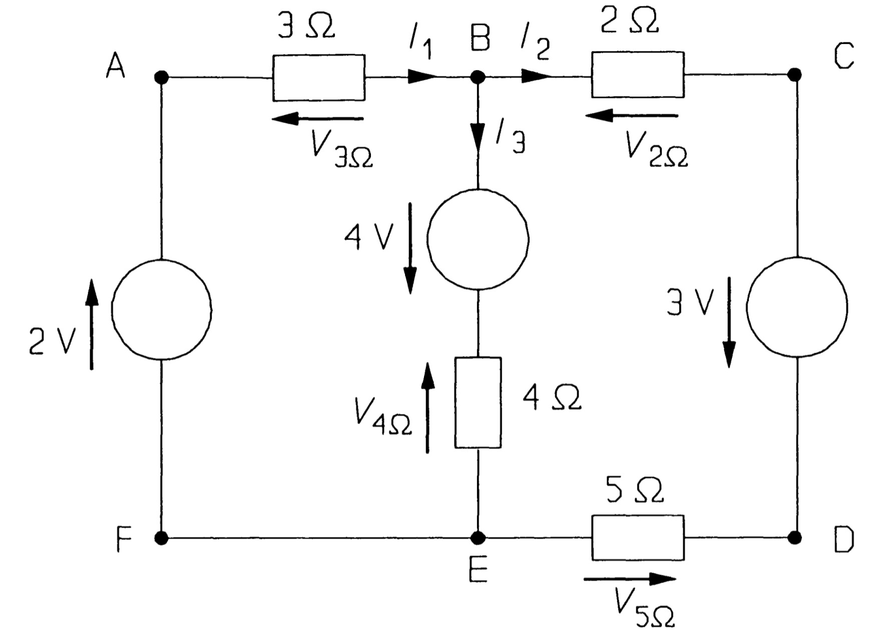
Selecting loop ABEFA, and taking clockwise-pointing voltages as positive and anticlockwise voltages as negative, we find:
\[ -V_{3\Omega}+4-V_{4\Omega}+2=0 ~~~~~~~~~~~~~~~~~~~~~~(1)\]
The choice of positive for clockwise voltages is arbitrary. Once you have assigned voltage arrows to the circuit elements (with voltage arrows on passive elements opposing the currents through them) you must wait until the analysis is complete to discover whether the polarity is 'right' (in which case the voltage will tum out to be positive) or 'wrong' (in which case the voltage will tum out to be negative). For loop ABCDEFA, KVL yields
\[-V_{3\Omega} -V_{2\Omega}+3-V_{5\Omega}+2=0 ~~~~~~~~~~~~~~~~~~~~(2)\]
and loop BCDEB produces
\[ -V_{2\Omega}+3-V_{5\Omega}+V_{4\Omega} -4=0 ~~~~~~~~~~~~~~~~~~~~~(3)\]
Note that subtracting equation 1 from equation 2 gives equation 3 - the application of KVL to this circuit produces only two independent equations. Voltages across the resistances can be found from Ohm's law; \(V_{3\Omega}\), for example, is \(3I_1\). Using this method equations 1 and 3 become
\[-3I_{1}-4I_{3}+6=0 ~~~~~~~~~~~~~~~~~~~~~~~~~~~(4)\\ -2I_{2}-5I_{2}+4I_{3}=0 ~~~~~~~~~~~~~~~~~~~~~~~~(5)\\ -7I_{2}+4I_{3}=0 ~~~~~~~~~~~~~~~~~~~~~~~~~~~(6)\]
Kirchhoff's current law is now needed to find a third equation for the unknown currents. If in figure we consider node B and take currents into the node as positive and currents out of the node as negative, then
\[I_{1}-I_{2}-I_{3}=0 ~~~~~~~~~~~~~~~~~~~~~~~~~~~~(7)\]
The three independent equations produced by application of Kirchhoff's and Ohm's laws to the circuit of figure are equation 4, 5 and 6, and solving these gives
\[I_1 = 1.017 A\]
\[I_2 = 0.279 A\]
\[I_3 = 0.738 A\]
The voltages across the resistances may be found from these currents with Ohm's law.
If inductances and capacitances are present Kirchhoff's laws can still be applied using the appropriate \(v-i\) relationships
\[v_L = L\frac{di}{dt}\]
and
\[v_C = \frac{1}{C} \int i~dt\],
which yield instantaneous values. (Kirchhoff's laws apply to direct, instantaneous and r.m.s. voltage and currents.) Kirchhoff's laws is used to decude useful results, starting with the addition of resistances, capacitances and inductances in series and in parallel.
Mesh analysis.
Mesh analysis applies KVL systematically to a circuit and produces simultaneous equations that may be solved to give the mesh currents. A mesh is a loop in a circuit with no loops inside it. Consider the circuit of the figure, which represents a domestic 2-phase supply common in North America. It contains three meshes: ABCDA, ADEFA, and CEDC; the large loop ABCDEF A is not a mesh as it can be divided into smaller loops. The meshes have been numbered 1, 2, and 3. Meshes one and two represent low-voltage circuits for lighting and appliances such as vacuum cleaners, hair dryers, etc., while mesh three represents a two-phase circuit for supplying relatively large loads. The 0.1\( \Omega \) resistances represent the wiring resistance.
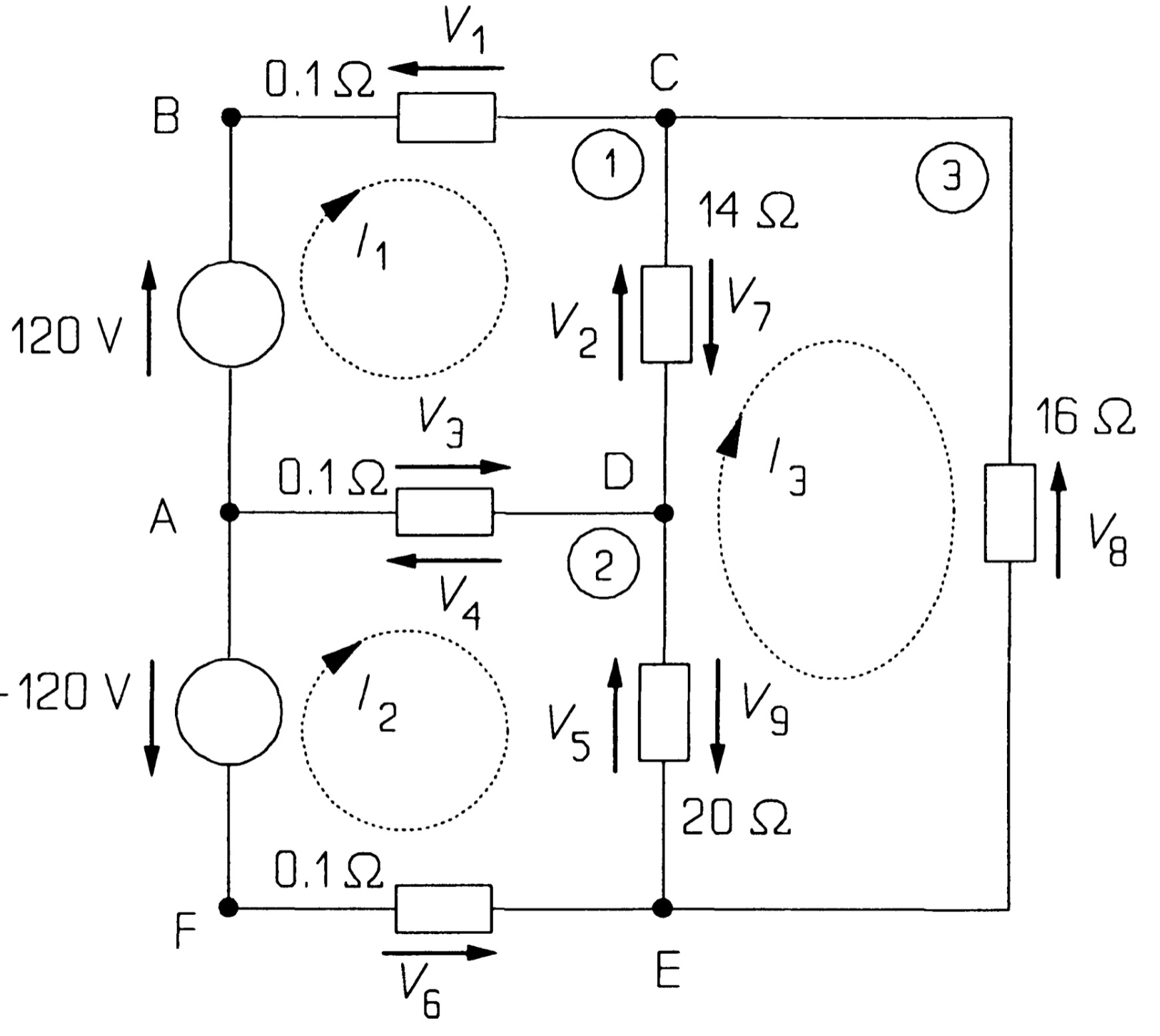
The first step in the analysis is to assign clockwise currents to each mesh: in this case, \( I_1 \), \( I_2 \), and \( I_3 \) to meshes 1, 2, and 3, respectively. The next step is to use KVL to find these currents. KVL around mesh 1 gives, with clockwise voltages taken as positive, anticlockwise negative:
\[ 120 - V_1 - V_2 - V_3 = 0 ~~~~~~~~~~~~~~~~~(1) \]
\( V_1 \) is the voltage across the 0.1\(\Omega\) resistance, which by Ohm's law is 0.1\( I_1 \). \( V_2 \) is the voltage across the 14\( \Omega \) resistance, which is not 14\( I_1 \), since the 14\( \Omega \) resistance is shared between meshes, and the resultant current flow from C to D must be \( (I_1 - I_3) \). \( V_2 \) must therefore be 14\( (I_1 - I_3) \). \( V_3 \) is the voltage across the middle 0.1\( \Omega \) resistance (the common wire for the two phases), which is shared between meshes 1 and 2. \( V_3 \) must then be 0.1\( (I_1 - I_2) \) and equation 1 becomes
\[ 120-0.1I_1 -14(I_1 - I_3)-0.1(I_1 - I_2)=0 ~~~~~~~~~~~~~~~~~(2) \]
or,
\[ 14.2I_1 - 0.1I_2 - 14I_3 = 120 ~~~~~~~~~~~~~~~~~(3) \]
after rearranging terms.
The use of KVL in mesh 2 yields
\[ -(-120) - V_4 - V_5 - V_6 = 0 ~~~~~~~~~~~~~~~~~(4) \]
The -120 V source points anticlockwise and is written -(-120) in equation 4 (if in doubt, reverse the arrow and the sign on this source, which leaves its value unchanged). \( V_4 \), the voltage across the middle 0.1 \( \Omega \) resistance, is 0.1 \( (I_2-I_1) \) by Ohm's law \( (V_4 = -V_3) \). \( V_5 \) is the voltage across the 20 \( \Omega \) resistance, and must be 20 \( (I_2-I_3) \) by Ohm's law, while \( V_6 \) is 0.1\( I_2 \), so that the equation becomes
\[ 120 - 0.1(I_2-I_1)-20(I_2-I_3)-0.1 I_3=0 ~~~~~~~~~~~~~~~~~(5) \]
which rearranges to
\[ -0.1I_1, + 20.2I_2 - 20I_3 = 120 ~~~~~~~~~~~~~~~~~(6) \]
Mesh 3 gives
\[V_7+V_8+V_9=0 ~~~~~~~~~~~~~~~~~(7)\]
Again, the voltages are found by using Ohm's law:
\[ V_7 = 14(I_3 - I_1) ~~~~~~~~~~~~~~~~~(8)\], \[ V_8 = 16I_3 ~~~~~~~~~~~~~~~~~(9)\] and \[ V_9 = 20(I_3 -I_2) ~~~~~~~~~~~~~~~~~(10)\].
Then, equation 7, after rearranging, is
\[ -14I_1 - 20I_2 + 50I_3 = 0 ~~~~~~~~~~~~~~~~~(11) \]
Three meshes have produced three equations, numbered 12, 13 and 14:
\[14.2I_1 - 0.1I_2- 14I_3 = 120 ~~~~~~~~~~~~~~~~~(12)\] \[ -0.1I_1 + 20.2I_2- 20I_3 = 120~~~~~~~~~~~~~~~~~(13)\] \[ -14I_1 - 20I_2 + 50I_3 = 0 ~~~~~~~~~~~~~~~~~(14)\]
Three meshes have produced three equations represented in matrix form:
\[ \begin{bmatrix} 14.2 & -0.1 & -14\\ -0.1 & 20.2 & -20\\ -14 & -20 & 50 \end{bmatrix} \begin{bmatrix} I_1 \\ I_2 \\ I_3 \end{bmatrix} = \begin{bmatrix} 120 \\ 120 \\ 0 \end{bmatrix} \]
And there are three unknown mesh currents. The solution is \( I_1 = 23.1 \) A, \( I_2 = 20.6 \) A and \( I_3 = 14.7 \) A.
The currents through the 14\( \Omega \) and 20\( \Omega \) loads are \( I_1 - I_3 (= 8.4 A) \) and \( I_2 -I_3 (= 5.9 A) \), while the common wire carries a relatively small current \( I_1 -I_2 (= 2.5 A) \). The power consumed by the 14\( \Omega \) load is \( 14 \times 8.42 = 990 W\) , by the 20\( \Omega \) load is \( 20 \times 5.92 = 700 \) W, and the 16 \( \Omega \) load consumes \( 16 \times 14.72 = 3.5 kW\) .
Take note of the form of equations 12, 13, and 14: The first comes from applying KVL to mesh 1, so the coefficient of \( I_1 \) is opposite in sign to those of the other two currents. The second equation arises from applying KVL to mesh 2, so the coefficient of \( I_2 \) is positive and the rest negative. The third equation comes from mesh 3, so the coefficient of \( I_3 \) is positive, the others negative. If the unknown currents and voltages are assigned in the systematic way described, the signs of the current coefficients should always follow this pattern - check if they do not! With a little practice, the student will find it superfluous to put voltages across resistances and will be able to write down the current equations directly. Aided by a computer solution of simultaneous equations, an experienced student can solve a 7-mesh problem in two to three minutes and get it right the first time.
Nodal analysis
While mesh analysis employs KVL systematically, nodal analysis uses KCL to give a set of simultaneous equations from which all the nodal voltages may be derived. Voltages are assigned to each principal node of a network, principal nodes being points where three or more branches of a circuit join. Strictly, a node is the point at which two or more branches join, and a principal node is one where three or more branches join.
Consider the circuit of the figure. The (principal) nodes are A, C, D, and E, with node A being chosen as the reference node. (The reference node need not be at ground potential, nor at any particular place in the circuit: the choice is arbitrary.) Voltages are then assigned to the other nodes representing the potential differences between them and the reference node: these are \( V_1 \), \( V_2 \), and \( V_3 \) in the figure. We then apply KCL at nodes C, D, and E. At node C, taking the current out of the node to be positive, we see that
\[ I_1 + I_2 + I_3 = 0 ~~~~~~~~~~~~~~~~~(1)\]
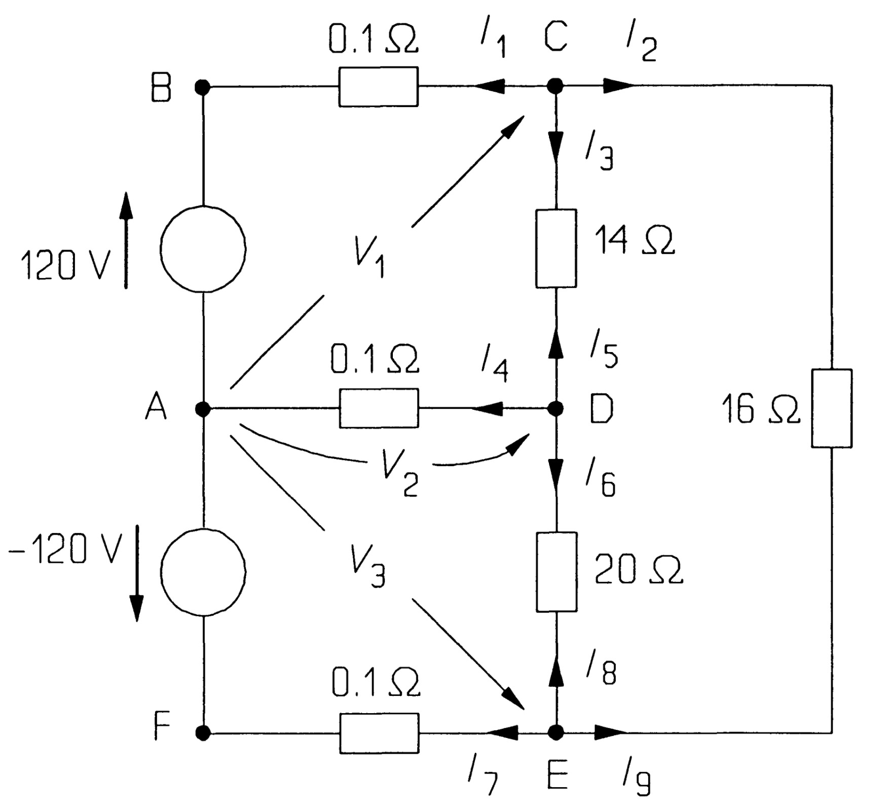
Now \( I_1 \) is the current through the uppermost 0.1\( \Omega \) resistance, which is given by Ohm's law as \( (V_1 - 120)/0.1 \) (make sure the sign is correct here!), since the voltage across the resistance is \( (V_1 - 120) \). Similarly, \( I_2 \) is \( (V_1 - V_3)/16 \) and \( I_3 \) is (V_1 - V_2)/l4. Equation 1 then becomes
\[ \frac{V_1 -120}{0.1}+\frac{V_1-V_3}{16}+\frac{V_1-V_2}{14}=0 ~~~~~~~~~~~~~~~~~(2) \]
At node D,
\[ I_4 + I_5 + I_6 = 0 ~~~~~~~~~~~~~~~~~(3)\]
Now \( I_4 = V_2 /0.1 \), as the middle 0.1\( \Omega \) resistance lies between the reference node A and node D, then \( I_5 = (V_2 - V_1)/14 \) (note that \( (I_5 = -I_3) \), but one should always give the currents at each node new identities, and work out afresh what they are) and \( ( I_6 = (V_2 - V_3)/20) \). Thus equation 3 is
\[ \frac{V_2}{0.1}+\frac{V_2-V_1}{14}+\frac{V_2-V_3}{20}=0 ~~~~~~~~~~~~~~~~~(4) \]
Finally, at node E
\[ I_7 + I_8 + I_9 = 0 ~~~~~~~~~~~~~~~~~(5)\]
where
\[ I_7 = (V_3 - (-120))/0.1 ~~~~~~~~~~~~~~~~~(6)\]
\[ I_8 = (V_3 - V_2)/20 ~~~~~~~~~~~~~~~~~(7)\]
\[ I_9 = (V_3 - V_1)/16 ~~~~~~~~~~~~~~~~~(8)\]
Substituting these values into equation 4 gives
\[ \frac{V_3 +120}{0.1}+\frac{V_3-V_2}{20}+\frac{V_3-V_1}{16}=0 ~~~~~~~~~~~~~~~~~(9) \]
Rearranging equations 2, 4 and 9 produces the three simultaneous equations.
\[ 10.13V_1 - 0.071V_2 - 0.0625V_3 = 1200 ~~~~~~~~~~~~~~~~~(10)\]
\[ -0.071 V_1 + 10.12V_2 - 0.05V_3 = 0 ~~~~~~~~~~~~~~~~~(11)\]
\[ -0.0625V_1 - 0.05V_2 + 10.11 V_3 = -1200 ~~~~~~~~~~~~~~~~~(12)\]
Three node equations are represented in matrix form:
\[ \begin{bmatrix} 10.13 & -0.071 & -0.0625\\ -0.071 & 10.12 & -0.05\\ -0.0625 & -0.05 & 10.11 \end{bmatrix} \begin{bmatrix} V_1 \\ V_2 \\ V_3 \end{bmatrix} = \begin{bmatrix} 1200 \\ 0 \\ 1200 \end{bmatrix} \]
The solution to the equations is \( V_1 = 117.7 \) V, \( V_2 = 0.24 \) V and \( V_3 = -118 \) V.
The form of these equations is worth remarking: the first comes from using KCL at node C, where the voltage relative to node A is \( V_1 \), and the only positive coefficient is that of \( V_1 \). The same pattern is followed in the other two equations. Any mistakes in sign should soon be noticed and put right if the equations are written in this systematic way. The solution to the equations is \( V_1 = 117.7 \) V, \( V_2 = 0.24 \) V and \( V_3 = -118 \) V. The voltage across the 14 \( \Omega \) load is \( 117.7- 0.24 = 117.5 \) V, and the current through it is \( 117.7/14 = 8.4 \) A, as before. The voltage across the 20 \( \Omega \) resistance is \( 0.24- (-118) = 118.2\) V, so the current through it is \( 5.9 \) A, and finally, the voltage across the 16 \( \Omega \) resistance is \( 117.7 -(-118) = 235.7 \) V, and the current through it is \( 14.7 \) A. The solution is, as it must be, the same as that found by mesh analysis earlier.
