Thevenin's theorem
Thevenin's theorem states
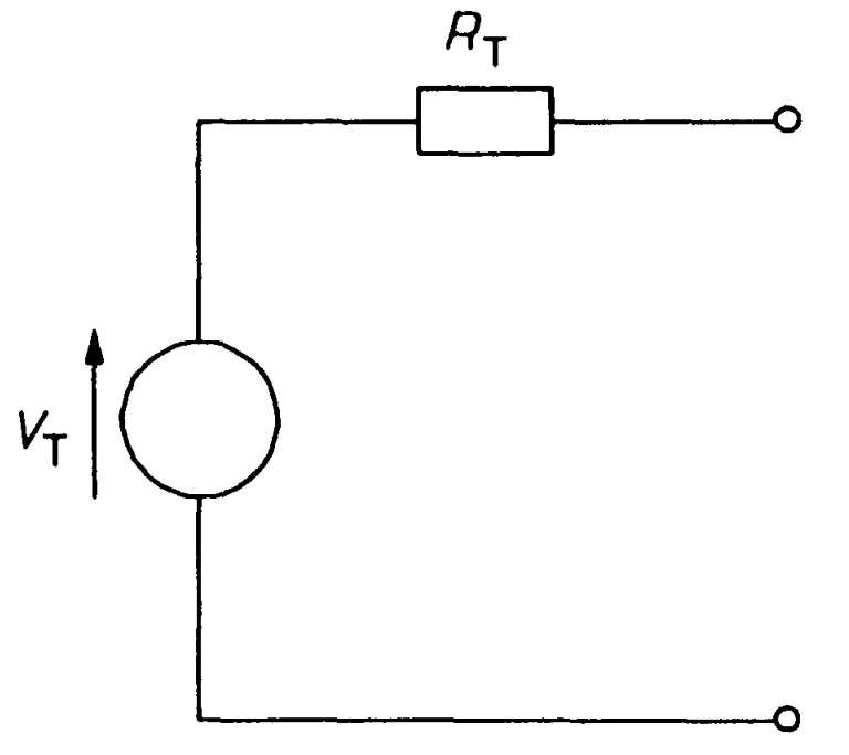
Any two-terminal, linear network of sources and resistances may be replaced by a single voltage source in series with a resistance. The voltage source has a value equal to the open-circuit voltage appearing at the terminals of the network. The resistance value is the resistance that would be measured at the network's terminals when all the sources have been replaced by their internal resistances.
Any two-terminal network containing a number of e.m.f. sources and resistances can be replaced by an equivalent series circuit having a voltage source \(E_0\) in series with a resistance \(R_0\) where,
\(E_0\) = open circuited voltage between the two terminals. \(E_0\) = the resistance between two terminals of the circuit obtained by looking “in” at the terminals with load removed and voltage sources replaced by their internal resistances, if any.
Proceedure
- (i) Open the two terminals (i.e. remove any load) between which you want to find Thevenin equivalent circuit.
- (ii) Find the open-circuit voltage between the two open terminals. It is called Thevenin voltage \(E_{0}\).
- (iii) Determine the resistance between the two open terminals with all ideal voltage sources shorted and all ideal current sources opened (a non-ideal source is replaced by its internal resistance). It is called Thevenin resistance, \(R_{0}\).
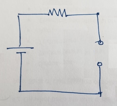
- (iv) Connect \(E_{0}\) and \(R_{0}\) in series to produce Thevenin equivalent circuit between the two terminals under consideration.
- (v) Place the load resistor removed in step (i) across the terminals of the Thevenin equivalent circuit. The load current can now be calculated using only Ohm’s law and it has the same value as the load current in the original circuit.
Thevenin's equivalent circuit is shown in figure. To replace complex networks by such a simple equivalent circuit can be highly convenient. For example let us find the Thevenin equivalent of the two-terminal network of figure. There are three steps in essence. First, is to determine the voltage across \(AB\). That is just the voltage across the \(4~\Omega\) resistance, which may be found by the voltage divider rule as the resistances are in series with the voltage source:
\[V_{AB} = V_{4\Omega} = 4 \times \frac{3}{6} = 2~V\]
This is the open-circuit voltage across \(AB\), and consequently the source voltage, \(V_T\), in the Thevenin equivalent circuit.
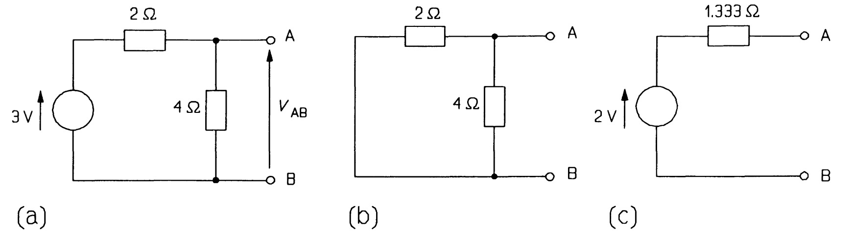
Secondly, the voltage source must be replaced by its internal resistance. As the voltage source is ideal and thus has zero internal resistance by definition, all this means is replace the voltage source by a short circuit. The circuit then becomes that of figure (b) simply two resistances in parallel when looked at from \(AB\). So, thirdly, we combine them by the product-over-sum rule:
\[R_{T} = \frac{2 \times 4}{2+4} = 1.333~\Omega \]
Hence the Thevenin equivalent of the network in figure (c). It is important to realise that the circuits of figures are equivalent only for measurements of current and voltage made at terminals \(A\) and \(B\), and nowhere else.
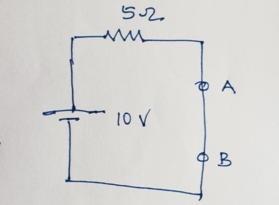
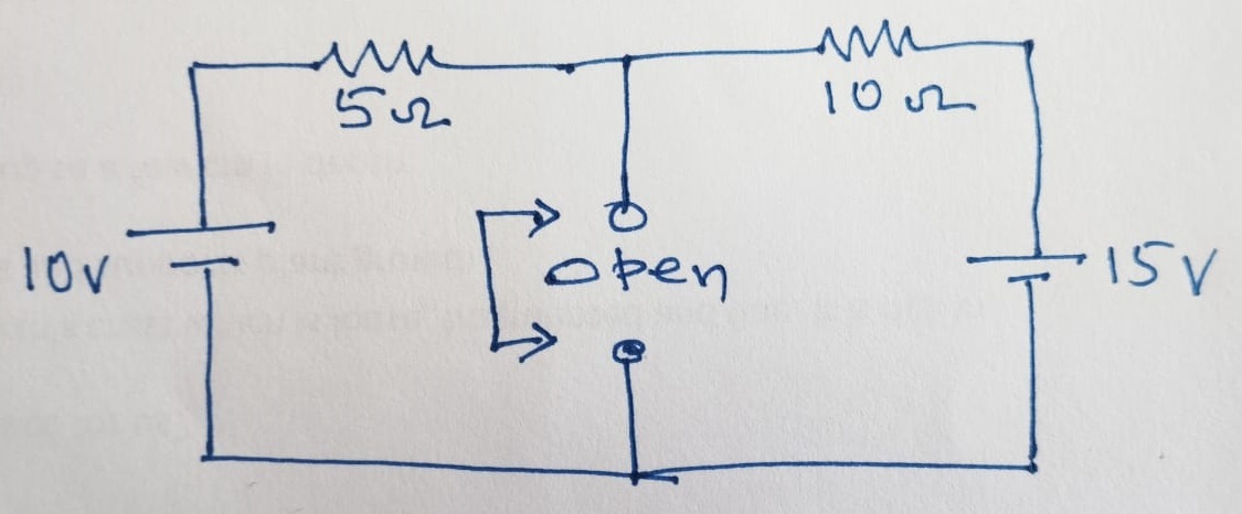
Find the current through the \(10~\Omega\) load resistance between \(A\) and \(B\) as given in the figure using Norton and Thevenin method.
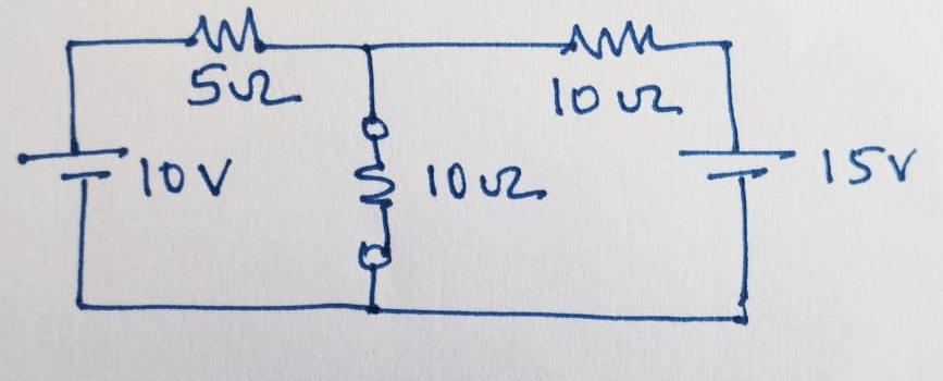
The first step using the Norton method is to remove the load resistance and short the terminal \(A\) and \(B\) and find the contibution of closed circuit current through terminals \(A\) and \(B\) for each of the voltage sources given. i.e., \(I_1\) for \(10~V\) and \(I_2\) for \(15~V\).
Hence, the \(I_1\) is calucalted as:
\[I_1 = \frac{10~V}{5~\Omega} = 2~A\]
\(I_2\) is calculated as:
\[I_2 = \frac{15~V}{10~\Omega} = 1.5~A \]
Hence, the total closed circuit current through the terminal \(A\) and \(B\) is the Norton current, \(I_1\), which is:
\[I_N=I_1+I_2 = 2~ A + 1.5~A = 3.5~A\]
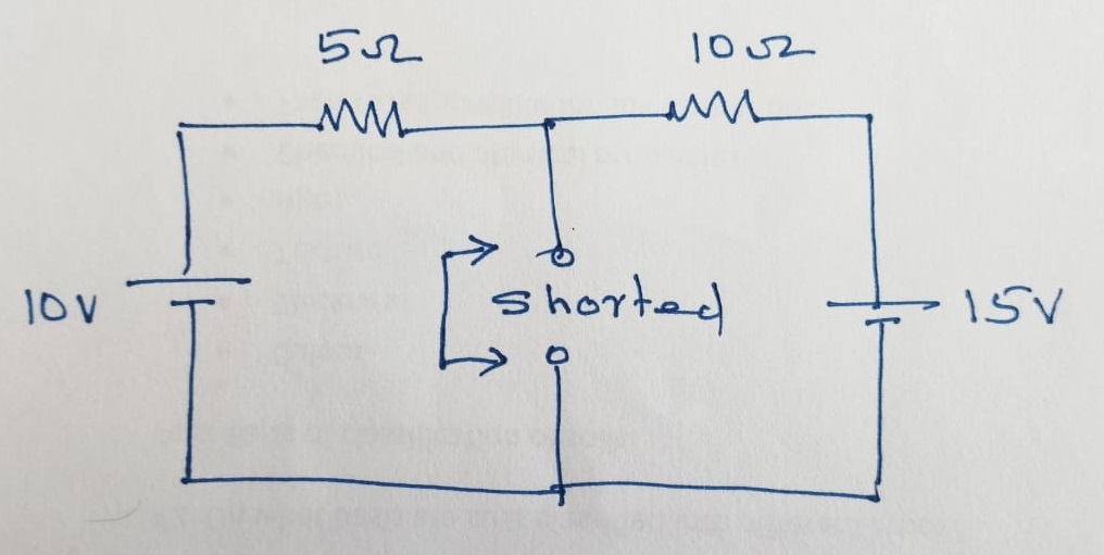
Now, let us estimate the Norton resistance, \(R_N\). The obtain the Norton resistance, the voltages should be shorted and current sources should be kept open. Here, we only have the voltage sources and the circuit given below shows the equivalent circuit with voltage lead shorted and the simplified form to estimate the \(R_N\).
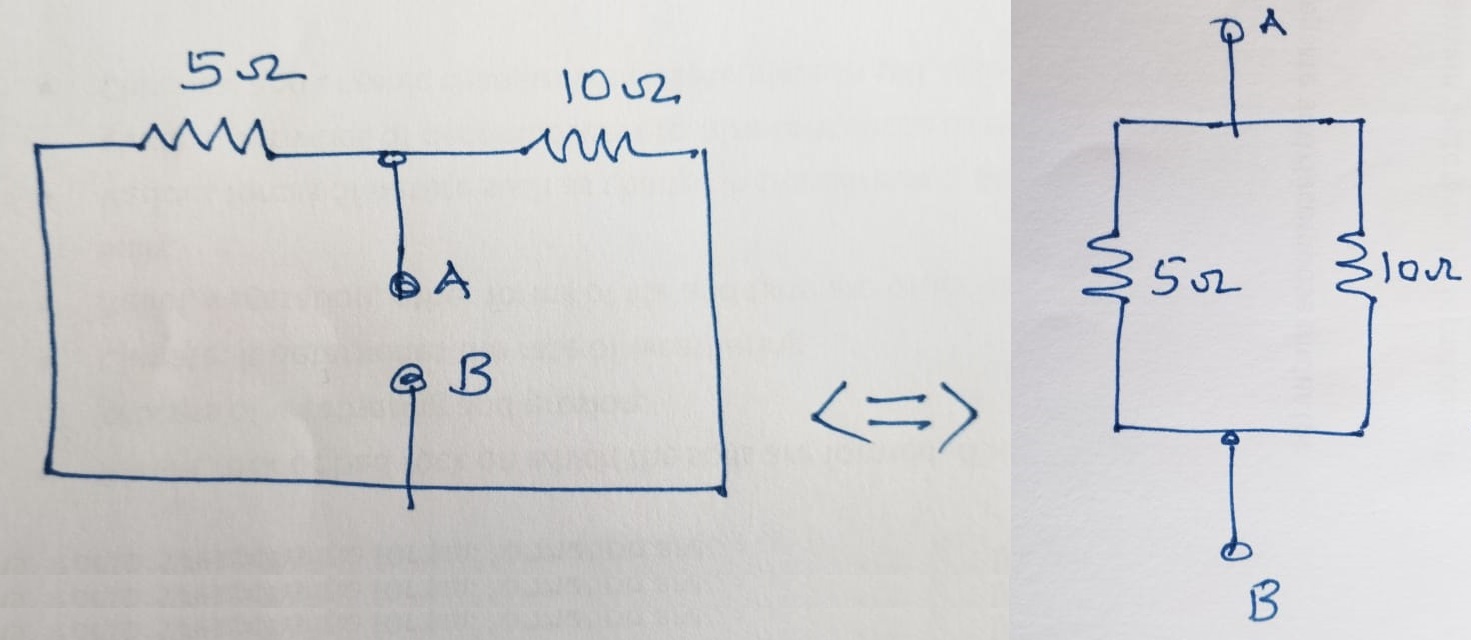
\(R_N\) is calculated as:
\[R_N = \frac{5\times 10}{5+10} = \frac{10}{3} = 3.333~\Omega \]
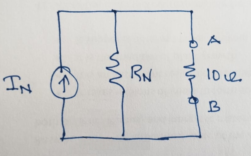
Now, we have the \(R_N\) and \(I_N\) as follows:
\[I_N = 3.5 ~A \\ R_N = 3.333 ~\Omega\]
The value of the current flowing through the load resistance (load current) is obtained by pluging back the \(6 ~\Omega\) resistance and by using the current division formula as follows:
\[I_L = I_N \left( \frac{R_N}{R_N+R_L}\right)\]
\[I_L = 3.5 ~A \left( \frac{3.333~\Omega}{[3.333+6]~\Omega}\right) = 1.25 ~A\]
Now, the total current flowing through the load resistance of \(6 ~\Omega\) is:
\[I_L = 1.25 ~A\]
The Thevenin voltage, \(V_{TH}\) is obtained from \(I_N\) and \(R_N\) as:
\[V_{TH}=I_N \times R_N \\ V_{TH}= 3.5 ~A \times 3.333 ~\Omega = 11.667 ~V \]
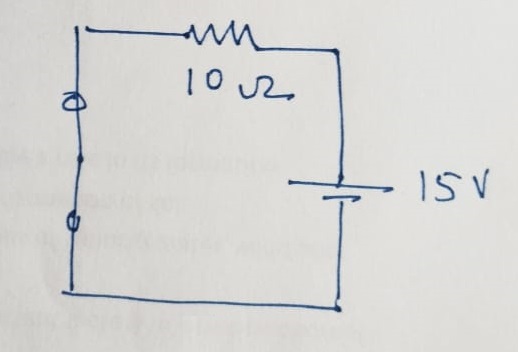
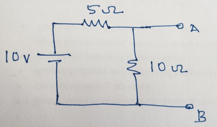
Now, let us Thevanize the same circuit as given below. Here, the terminals \(A\) and \(B\) should be kept open after removing the load resistance \(R_L\) to find the open circuit voltage due to each of the voltage sources given seperately.
The contribution of open circuit voltage due to 10 V is calculated as:
\[V_1 = \frac{10 ~V}{10~\Omega + 5~\Omega}\times 10 ~\Omega = 6.667~V\]
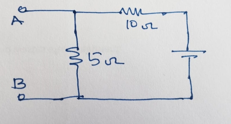
The contribution of open circuit voltage due to 15 V is calculated as:
\[V_1 = \frac{15 ~V}{10~\Omega + 5~\Omega}\times 5 ~\Omega = 5.00 ~V\]
The total contribution of open circuit voltage due to 10 V and 15 V is calculated as:
\[V_{TH} = V_1 +V_2 = 6.667 + 5.00 ~V = 11.667 ~V\]
while,
\[R_N = R_{TH}\]
Hence,
\[R_{TH} = 3.333~\Omega \]
Now, the total current flowing through the load resistance of \(6 ~\Omega\) will be obtained as:
\[I_L = \frac{11.667 ~V}{3.333~\Omega + 6~\Omega} = 1.25 ~A\]