Norton's theorem
Norton's theorem is a useful complement to Thevenin's:
Any two-terminal, linear network of sources and resistances may be replaced by a single current source in parallel with a resistance. The value of the current source is the current flowing between the terminals of the network when they are short-circuited. The value of the resistance is the resistance measured at the terminals of the network when all sources have been replaced by their internal resistances.
Norton's equivalent circuit is shown in figure.
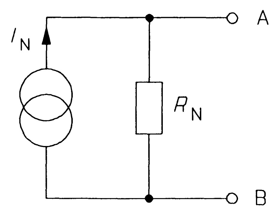
Any network having two terminals \(A\) and \(B\) can be replaced by a current source of output IN in parallel with a resistance \(R_N\).
- (i) The output \(I_N\) of the current source is equal to the current that would flow through AB when terminals \(A\) and \(B\) are short circuited.
- (ii) The resistance \(R_N\) is the resistance of the network measured between terminals \(A\) and \(B\) with load (\(R_L\)) removed and sources of e.m.f. replaced by their internal resistances, if any.
Norton’s theorem is converse of Thevenin’s theorem in that Norton equivalent circuit uses a current generator instead of voltage generator and resistance \(R_N\) (which is the same as \(R_0\)) in parallel with the generator instead of being in series with it.
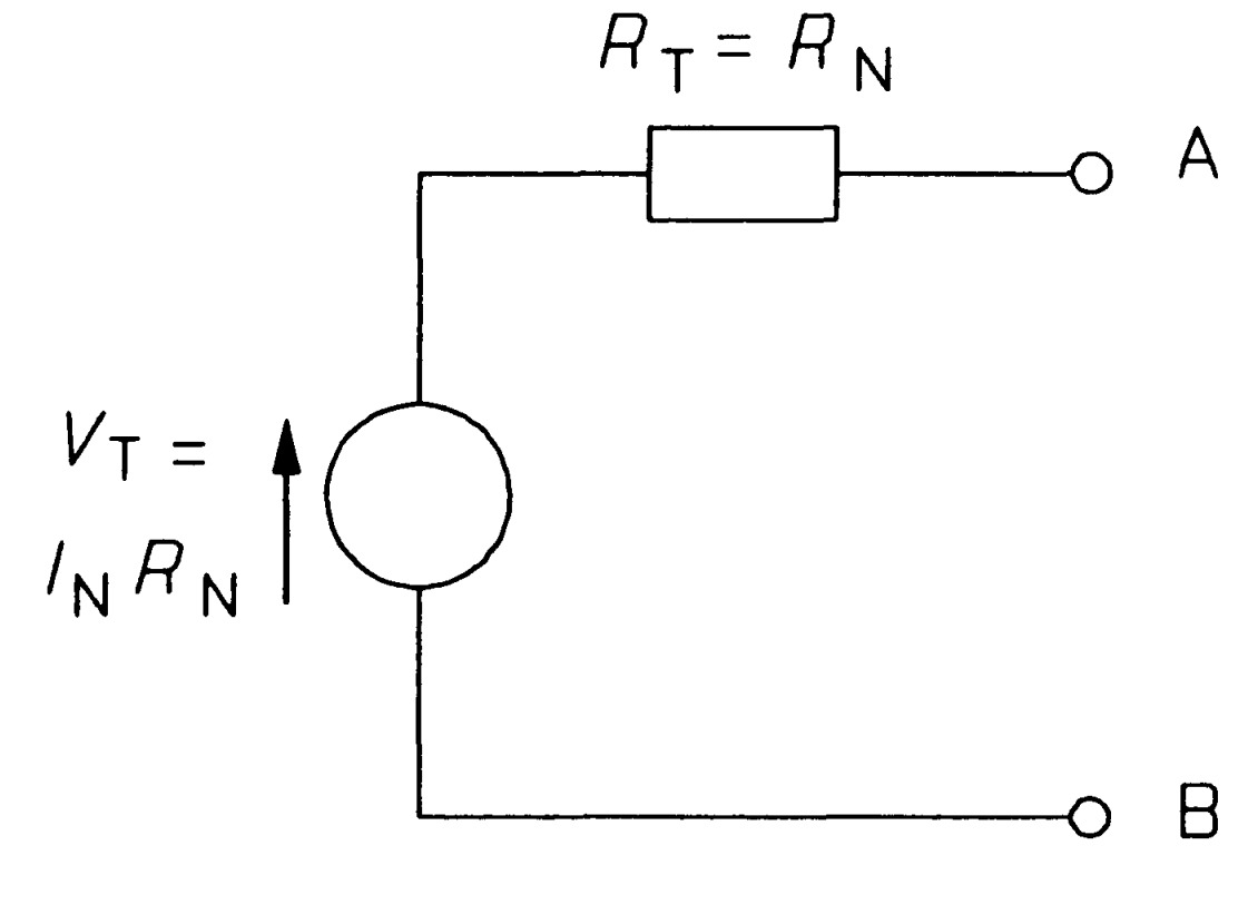
Any two-terminal network of sources and resistances may be replaced by this AB. Since Thevenin's theorem applies to any two-terminal network, it must apply to Norton's equivalent circuit too. The Thevenin equivalent of Norton's circuit can be derived as follows: In figure the open-circuit voltage is that across \(R_{N}\), which must be \(I_{N}R_{N}\) since all the current from the source flows through it. Therefore
\[V_{T}=I_{N}R_{N}\]
The next step is to replace the source by its internal resistance - infinity for an ideal current source by definition - which amounts to open-circuiting an ideal current source. On doing this we are left with RN alone connected across AB, so the Thevenin resistance is identical to the Norton resistance:
\[R_{T}=R_{N}\]
Figure shows the transformation, which requires only the calculation of \(V_T=I_{N}R_{N}\), the open-circuit voltage of Norton's equivalent circuit. We must decide for ourselves whether we use the Norton or the Thevenin form of equivalent circuit. As a general rule one should use the Norton circuit to combine parallel sources and the Thevenin circuit to combine series sources.
Procedure
- (i) Open the two terminals (i.e. remove any load) between which we want to find Norton equivalent circuit.
- (ii) Put a short-circuit across the terminals under consideration. Find the short-circuit current flowing in the short circuit. It is called Norton current, \(I_{N}\).
- (iii) Determine the resistance between the two open terminals with all ideal voltage sources shorted and all ideal current sources opened (a non-ideal source is replaced by its internal resistance). It is called Norton’s resistance, \(R_N\). It is easy to see that \(R_N = R_0\).
- (iv) Connect \(I_{N}\) and \(R_{N}\) in parallel to produce Norton equivalent circuit between the two terminals under consideration.
- (v) Place the load resistor removed in step (i) across the terminals of the Norton equivalent circuit. The load current can now be calculated by using current-divider rule. This load current will be the same as the load current in the original circuit.
Hence, the current through the load resistance will be given by the Current division rule
\[I_L = I_N \left(\frac{R_N}{R_N + R_L}\right)\]
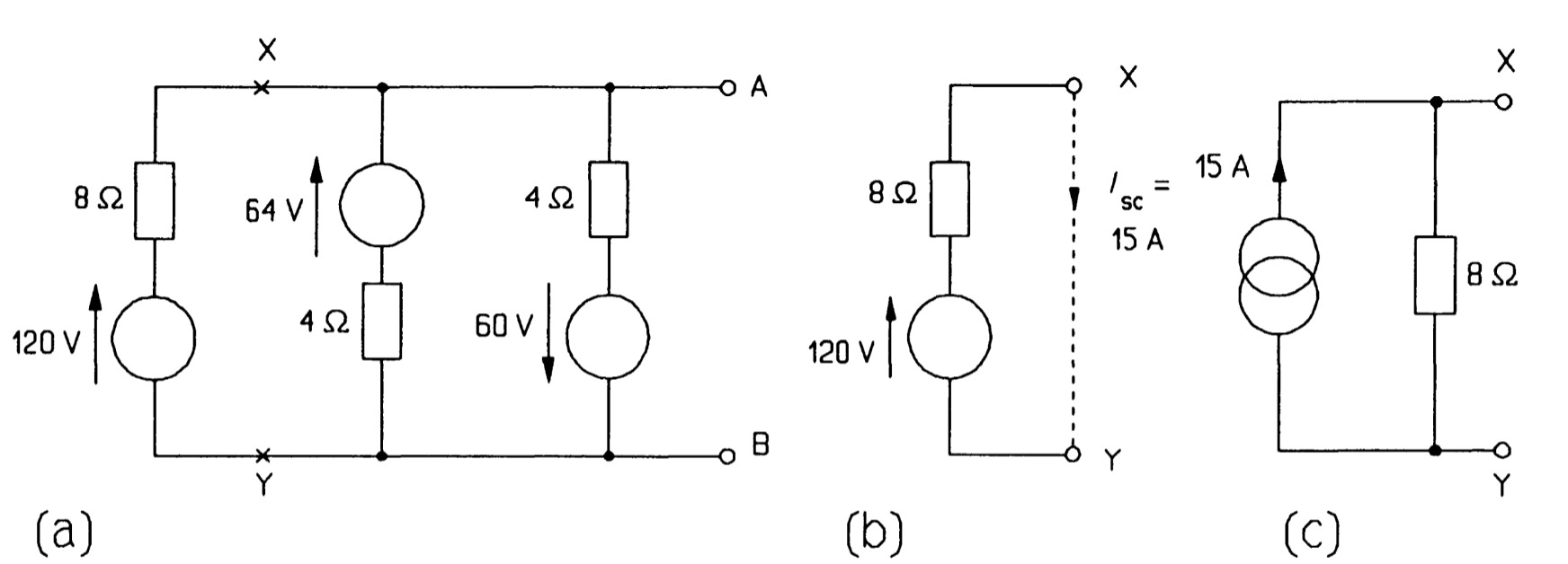
For example, consider the three generators in parallel in figure. We proceed by cutting the circuit at \(XY\) and looking at the source on the left by itself, as in figure. This source is in Thevenin form and must be transformed to the Norton form to enable us to add the parallel sources. The Norton source current is the current flowing through a short circuit across \(XY\), which is \(120/8 = 15 A\), by Ohm's law; and the Norton resistance is equal to the Thevenin resistance, \(8~\Omega\). So the Norton form of the 120 V source is as in figure. Note that the current arrow has the same direction as the voltage arrow of the original source. It is a good idea if in doubt to check this by examining which way current would flow through the short-circuited terminals. Having transformed the source we can re-attach it to the network at \(XY\) as in figure. The next voltage source is then transformed (it makes no difference which way round the voltage source and its series resistance are placed), and finally the one nearest to \(AB\). In the latter case the Norton equivalent must have its current arrow pointing down, like the voltage source it replaced. Figure shows the circuit at this stage.
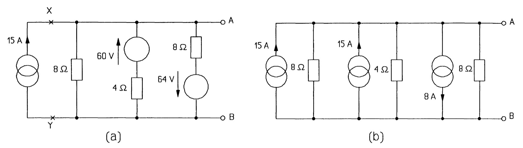
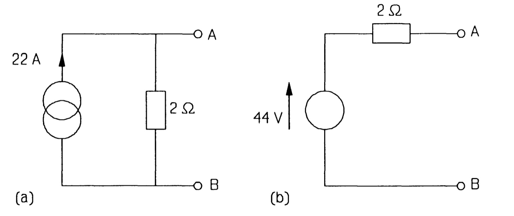
The three parallel current sources can now be added algebraically to give a single source of \(15 + 15- 8 = 22 A\). The third current source's value is subtracted from the other two as its direction is down and not up. Then the three parallel resistances in figure are combined to give a single 2\(\Omega\) resistance (by adding the reciprocals and taking the reciprocal of the result), giving the Norton circuit of figure . Finally the Norton circuit is turned into the Thevenin circuit of figure, using \(V_T = I_NR_N\).
Thevenin's and Norton's theorems enable us to take in principle any circuit inside a 'black box', make a measurement of the open-circuit voltage at its terminals, then the short-circuit current between them and from this represent the unknown contents of the box in the form of either equivalent circuit
Thevenin’s to Norton’s equivalent circuit
As mentioned previously, the Norton’s theorem is converse of Thevenin’s theorem and vice-versa, the Norton's equivalent circuit can be converted into Thevenin's equivalent circuit and back. The method of conversion is given below:
- (i) To convert Thevenin’s equivalent circuit into Norton’s equivalent circuit, \[I_N = E_0/R_0 ; \\ R_N = R_0\]
- (ii) To convert Norton’s equivalent circuit into Thevenin’s equivalent circuit \[E_0 = I_N R_N ; \\ R_0 = R_N\]
