Diode Clippers
There are a variety of diode networks called clippers that have the ability to clip off a portion of the input signal without distorting the remaining part of the alternating waveform. Depending on the orientation of the diode, the positive or negative region of the input signal is clipped off.
Clippers are networks that employ diodes to clip away a portion of an input signal without distorting the remaining part of the applied waveform.
There are two general categories of clippers: series and parallel. In the series configuration, the diode is in series with the load, whereas in the parallel configuration, the diode is in a branch parallel to the load.
Series Clipper
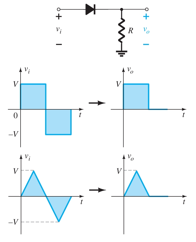
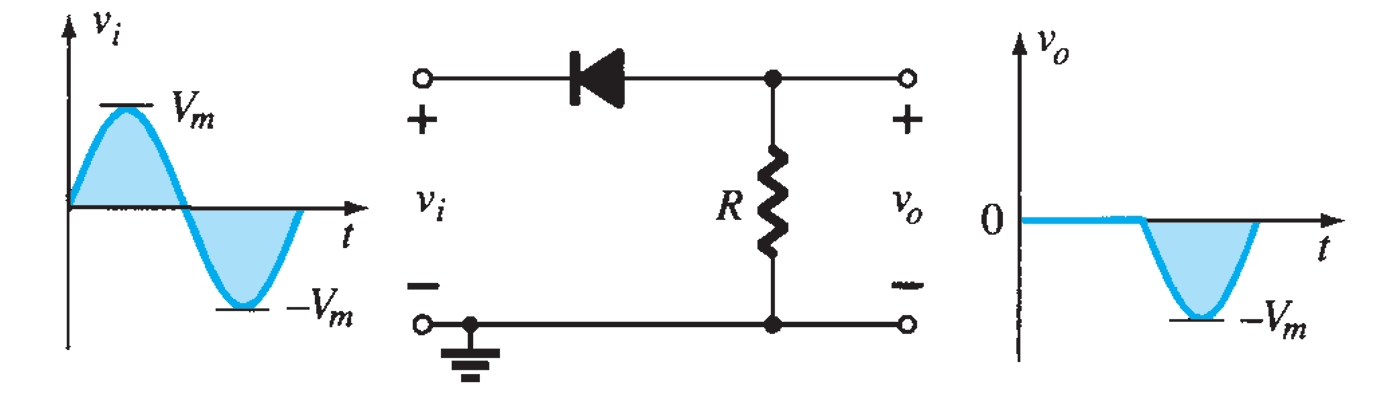
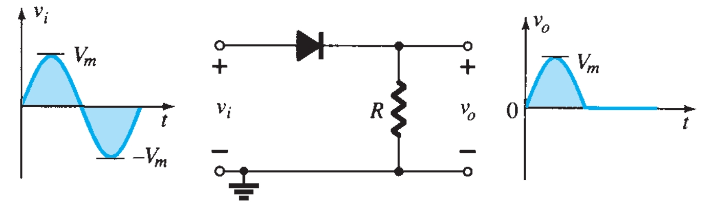
The response of the series configuration to a variety of alternating waveforms is provided in Fig. 1. Although first introduced as a half-wave rectifier (for sinusoidal waveforms), there are no boundaries on the type of signals that can be applied to a clipper.
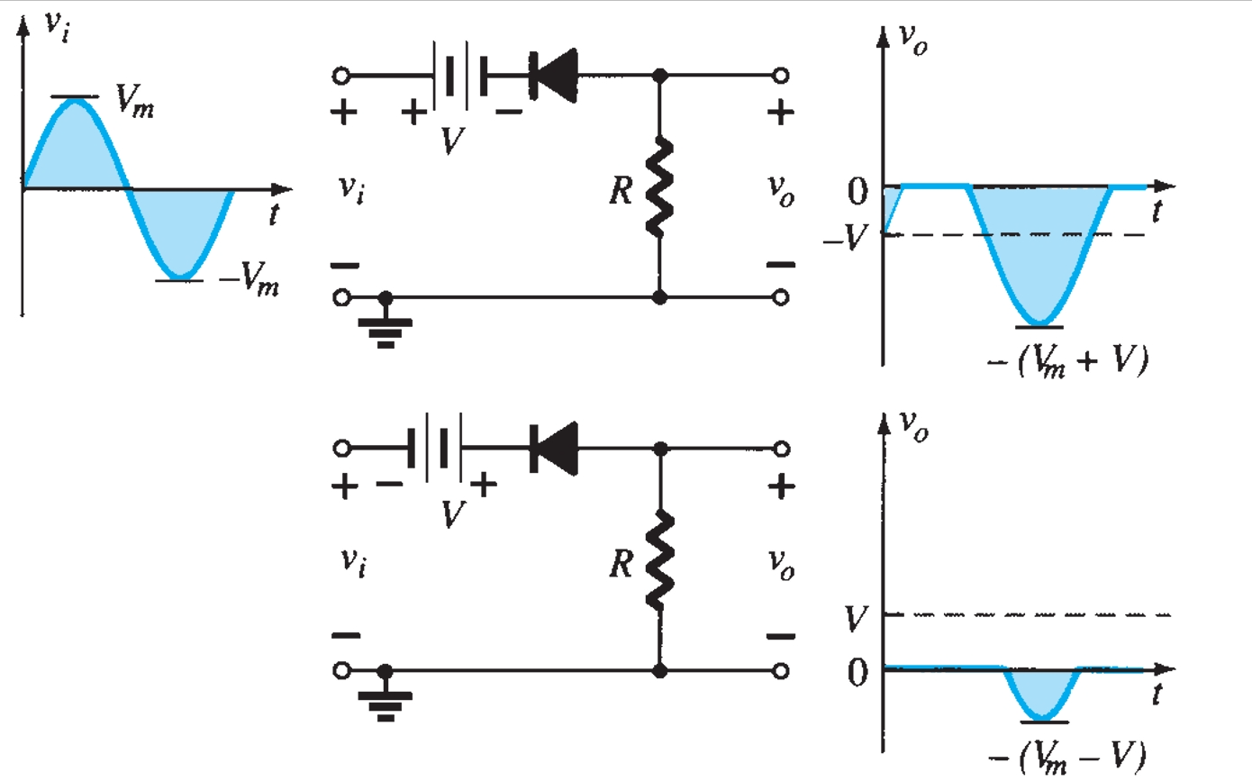
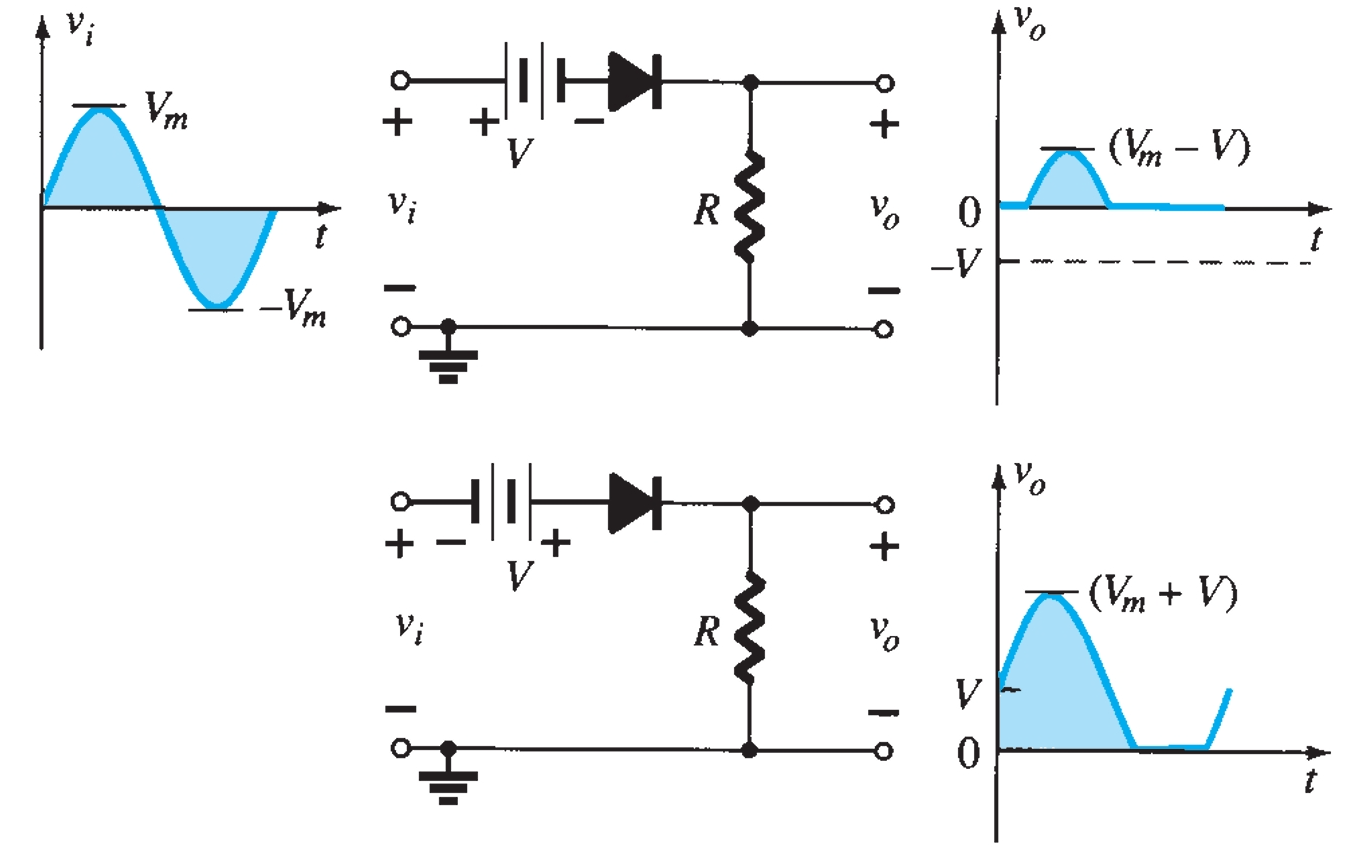
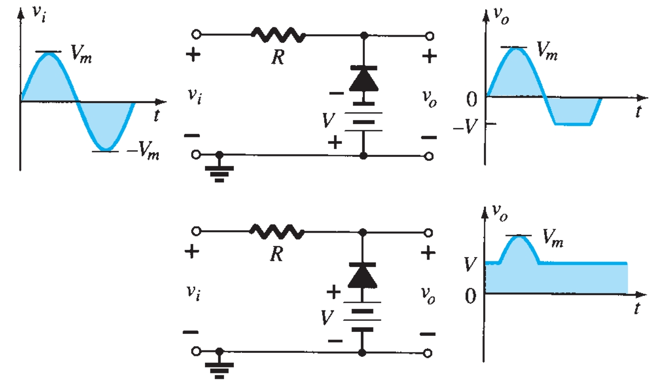
The addition of a DC supply, such as shown in Fig. 2, can have a pronounced effect on the output of a clipper. For the network of Fig. 1, the direction of the diode suggests that the signal \(v_i\) must be positive to turn it on. The DC supply further requires that the voltage \(v_i\) be greater than \(V\) volts to turn the diode on. The negative region of the input signal is pressuring the diode into the off state, which is further supported by the DC supply. In general, therefore, we can be quite sure that the diode is an open circuit (off state) for the negative region of the input signal. For an input voltage greater than \(V\) volts, the diode is in the short-circuit state, while for input voltages less than \(V\) volts, it is in the open-circuit or off state. When the diode is in the short-circuit state, the output voltage vo can be determined by :
\[v_o = v_i - V\]
An instantaneous value of \(v_i\), the input, can be treated as a DC supply of that value, and the corresponding DC value (the instantaneous value) of the output can be determined.
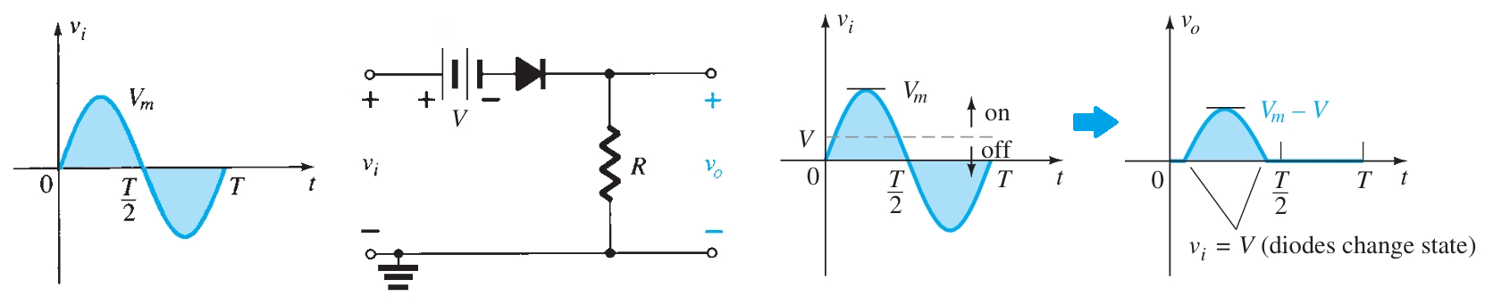
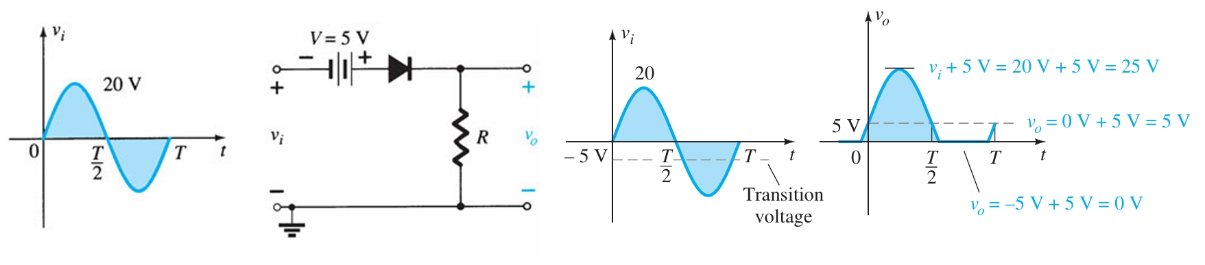
For instance, at \(v_i = V_m\), the network to be analyzed is as shown in Fig. 2. For \(V_m > V\), the diode is in the short-circuit state, and \(vo\) is as shown in Fig. 3.
\[v_o = V_m - V\]
At \(v_i = V\) the diodes change state; at \(v_i = -V_m\), \(v_o = 0~V\) and the complete curve for \(vo\) can be sketched as shown in Fig. 3.
Parallel Clipper
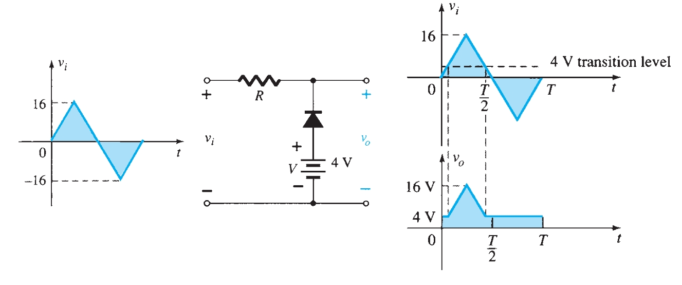
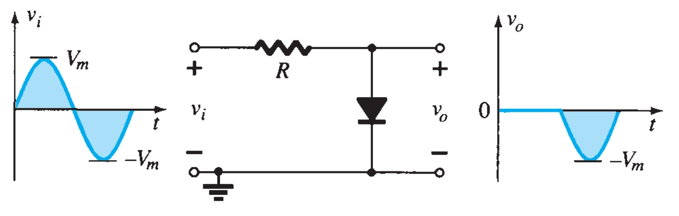
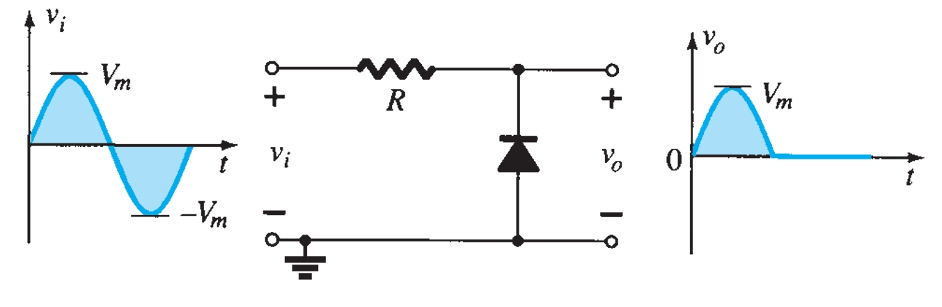
The network in Fig. 4 is the simplest parallel diode configuration, with the same output for any given input. The analysis of parallel configurations is very similar to that applied to series configurations. The polarity of the DC supply and the direction of the diode strongly suggest that the diode will be in the on state for the negative region of the input signal. For this region, the network has the diode short-circuited (on), where the defined terminals for \(v_o\) require that \(v_o = V = 4 ~V\).
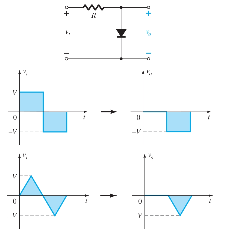
Since the DC supply is obviously pressuring the diode to stay in the short circuit state, the input voltage must be greater than \(4 ~V\) for the diode to be in the off state. Any input voltage less than \(4 ~V\) will result in a short-circuited diode.
In the open-circuit state, the network has the diode in the off state, so \(v_o = v_i\). Completing the sketch of \(v_o\) results in the waveform of Fig. 4.
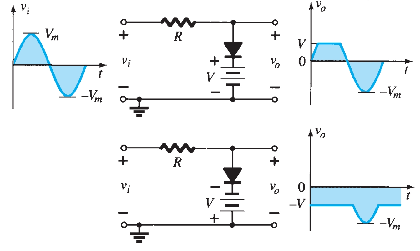
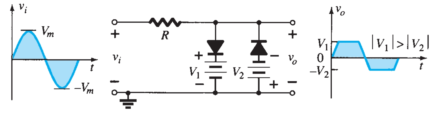
Clipper Circuits
Various configurations of output waveforms are obtained using the combination of series and parallel clippers, which are given below:
Diode Rectifier Circuits
The electric power available is usually an a.c. supply for reasons associated with the economics of generation and transmission. The supply voltage varies sinusoidally and has a frequency of 50 Hz. It is used for lighting, heating, and electric motors. But there are many applications (e.g., electronic circuits) where d.c. supply is needed. When such a d.c. supply is required, the mains a.c. Supply is rectified by using crystal diodes. The following two rectifier circuits can be used : (i) Half-wave rectifier, (ii) Full-wave rectifier.
Half-Wave Rectifier
In half-wave rectification, the rectifier conducts current only during the positive half-cycles of the input a.c. supply. The negative half-cycles of a.c. supply is suppressed, i.e., during negative half-cycles, no current is conducted, and hence no voltage appears across the load. Therefore, current always flows in one direction (i.e., d.c.) through the load, alternating every half-cycle.
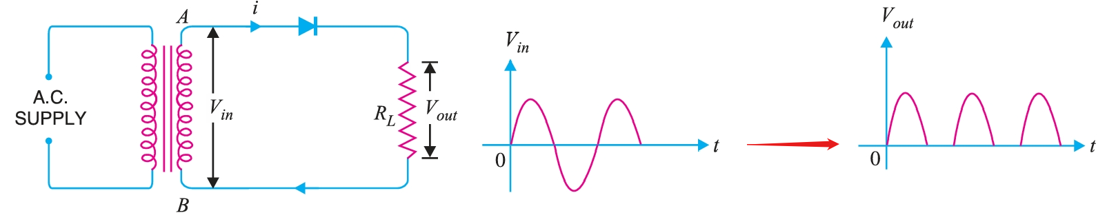
Fig. 14 shows the circuit where a \(p-n\) junction diode acts as a half-wave rectifier. The a.c. supply to be rectified is applied in series with the diode and load resistance \(R_{L}\). Generally, a.c. supply is given through a transformer. The use of a transformer permits two advantages. Firstly, it allows us to step up or step down the a.c. input voltage as the situation demands. Secondly, the transformer isolates the rectifier circuit from the power line, thereby reducing the risk of electric shock.
The a.c. voltage across the secondary winding AB changes polarity after every half-cycle. During the positive half-cycle of input a.c. voltage, end \(A\) becomes positive w.r.t. end \(B\). This makes the diode forward-biased, and hence it conducts current. During the negative half-cycle, end \(A\) is negative w.r.t. end \(B\). Under this condition, the diode is reverse-biased biased and it conducts no current. Therefore, current flows through the diode during the positive half-cycles of the input a.c. voltage only; it is blocked during the negative half-cycles. In this way, current through the load \(R_{L}\) always flows in the same direction. Hence d.c. output is obtained across \(R_{L}\). It may be noted that output across the load is pulsating d.c. These pulses are known as ripple voltage. The output frequency of a half-wave rectifier is equal to the input frequency (50 Hz).
Advantages
The main advantages of a half-wave rectifier are :
- (i) Requires only one diode for operation, making the circuit very simple and so it is economical.
- (ii) It is easy to construct, compact and lightweight and easy to understand.
- (iii) Useful for low-power applications
Disadvantages
The main disadvantages of a half-wave rectifier are :
- (i) The pulsating current in the load contains an alternating component whose basic frequency is equal to the supply frequency. Therefore, an elaborate filtering is required to produce a steady direct current.
- (ii) The a.c. supply delivers power only half the time. Therefore, the output is low.
Efficiency of Half-Wave Rectifier
The ratio of d.c. power output to the applied input a.c. power is known as rectifier efficiency, i.e.
\[\text{Rectifier efficiency, } \eta = \frac{\text{d.c. power output}}{\text{Input a.c. power}}\]
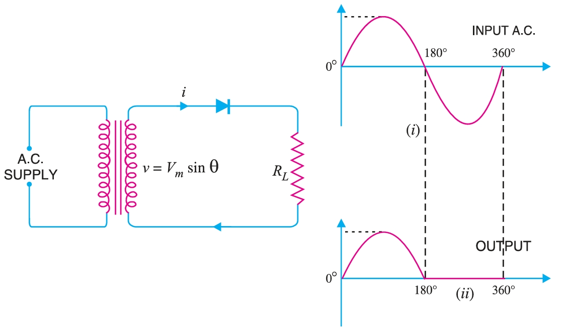
Consider a half-wave rectifier shown in Fig 15. The alternating voltage and current that appears across the secondary winding is given as:
\[V(\theta) = V_{m} \sin \theta \\ i(\theta) = I_{m} \sin \theta\]
where
\[I_m =\frac{V_m}{(r_d+R_L)}\]
Let \(r_{d}\) and \(R_{L}\) be the diode resistance and load resistance, respectively. The diode conducts during the positive half-cycles of a.c. supply while no current flows during the negative half-cycles.
- d.c. power The output current is a pulsating direct current. Therefore, in order to find d.c. power, the average current must be determined. \[I_{av} = I_{dc} = \frac{1}{2\pi} \int_0^{2\pi} i ~d\theta = \frac{1}{2\pi} \int_0^{2\pi} \frac{V_m}{(r_d+R_L)} \sin\theta ~d\theta\] \[I_{dc} = \frac{1}{2\pi} \left[\int_0^{\pi} \frac{V_m}{(r_d+R_L)} \sin\theta ~d\theta + \int_{\pi}^{2\pi} \frac{0}{(r_d+R_L)} \sin\theta ~d\theta \right] \] \[I_{dc} = \frac{1}{2\pi} \left[\int_0^{\pi} \frac{V_m}{(r_d+R_L)} \sin\theta ~d\theta + 0 \right] \] \[I_{dc} = \frac{V_m}{2\pi(r_d+R_L)} \int_0^{\pi} \sin\theta ~d\theta \] \[I_{dc} = \frac{V_m}{2\pi(r_d+R_L)}[-\cos\theta]_0^\pi \] \[I_{dc} = \frac{V_m}{2\pi(r_d+R_L)} \times 2 = \frac{V_m}{(r_d+R_L)}\frac{1}{\pi}\] \[I_{dc} = \frac{I_m}{\pi} \] \[\text{d.c. power, } P_{dc} = I_{dc}^2 R_{L}\] \[P_{dc} = \left(\frac{I_m}{\pi}\right)^2 R_{L}\]
- a.c. power input The current through the half wave rectifier circuit, \(I_{rms}\) is given as: \[I_{rms} = \sqrt{\frac{1}{2\pi} \int_0^{\pi} i^2 ~d\theta}\] \[I_{rms} = \sqrt{\frac{1}{2\pi} \int_0^{\pi} I_{m}^2 \sin^{2}\theta ~d\theta}\] \[I_{rms} = \sqrt{\frac{I_{m}^2}{2\pi} \int_0^{\pi} \sin^{2}\theta ~d\theta}\] \[I_{rms} = \sqrt{\frac{I_{m}^2}{2\pi} \int_0^{\pi} \sin^{2}\theta ~d\theta}\] \[I_{rms} = \sqrt{\frac{I_{m}^2}{2\pi} \int_0^{\pi} \left(\frac{1 - \cos~2\theta}{2}\right) ~d\theta}\] \[I_{rms} = \sqrt{\frac{I_{m}^2}{2\pi} \left[ \frac{\theta}{2} - \frac{1}{4}\sin~2\theta \right]_0^{\pi}}\] \[I_{rms} = \sqrt{\frac{I_{m}^2}{2\pi} \left[ \frac{\pi}{2} - \frac{1}{4}\sin(2\pi) \right]}\] \[I_{rms} = \sqrt{\frac{I_{m}^2}{2\pi} \left[ \frac{\pi}{2} \right]}\] \[I_{rms} = \sqrt{\frac{I_{m}^2}{4}}\] \[I_{rms} = \frac{I_{m}}{2}\] The a.c. power input is given by : \[\text{a.c. power, } P_{ac} = I_{rms}^2 (r_d+R_{L})\] For half wave rectified wave, \(I_{rms} = \left(\frac{I_m}{2}\right)\) \[\therefore\qquad P_{ac} = \left(\frac{I_m}{2}\right)^2 (r_d+R_{L})\]
- Rectifier efficiency \[\therefore \qquad \text{Rectifier efficiency} = \frac{\text{d.c. output power}}{\text{a.c. input power}}\] \[\eta= \frac{\left(\frac{I_m}{\pi}\right)^2 R_{L}}{\left(\frac{I_m}{2}\right)^2(r_d+R_{L})}\] \[\eta = \frac{4}{\pi^2} \left[\frac{R_{L}}{(r_d+R_{L})}\right] = 0.406~\left[\frac{R_{L}}{(r_d+R_{L})}\right]\] \[\eta = \frac{0.406}{\left(1+\frac{r_d}{R_{L}}\right)}\]
The efficiency will be maximum if \(r_d\) is negligible as compared to \(R_{L}\).
\[\therefore\qquad \qquad \text{Max. rectifier efficiency} = 40.6 \%\] This shows that in half-wave rectification, a maximum of \(40.6 \%\) of a.c. power is converted into d.c. power.
Full-Wave Rectifier
In full-wave rectification, current flows through the load in the same direction for both half-cycles of input a.c. voltage. This can be achieved using two diodes that alternate. For the positive half-cycle of the input voltage, one diode supplies current to the load, and for the negative half-cycle, the other diode does so; current is always in the same direction through the load. Therefore, a full-wave rectifier utilises both half-cycles of input a.c. voltage to produce the d.c. output. The following two circuits are commonly used for full-wave rectification : (i) Centre-tap full-wave rectifier, (ii) Full-wave bridge rectifier
Centre-Tap Full-Wave Rectifier
The circuit employs two diodes, \(D1\) and \(D2\), as shown in Fig. 16. A centre-tapped secondary winding \(AB\) is used with two diodes connected so that each uses one half-cycle of input a.c. voltage. In otherwords, diode \(D1\) utilises the a.c. voltage appearing across the upper half (\(OA\)) of the secondary winding for rectification, while diode \(D2\) uses the lower half winding \(OB\).
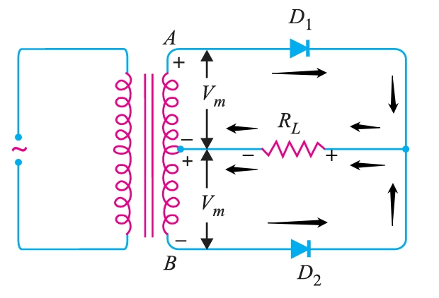
During the positive half-cycle of the secondary voltage, the end \(A\) of the secondary winding becomes positive, and end \(B\) becomes negative. This makes the diode \(D1\) forward-biased and the diode \(D2\) reverse-biased. Therefore, diode \(D1\) conducts while diode \(D2\) does not. The conventional current flow is through diode \(D1\), load resistor \(R_{L}\), and the upper half of the secondary winding, as shown by the dotted arrows. During the negative half-cycle, end \(A\) of the secondary winding becomes negative, while end \(B\) becomes positive. Therefore, diode \(D2\) conducts while diode \(D1\) does not. The conventional current flow is through diode \(D2\), load \(R_{L}\), and the lower half winding, as shown by solid arrows. The current in the load \(R_L\) is in the same direction for both half-cycles of input a.c. voltage. Therefore, d.c. is obtained across the load \(R_L\). Also, the polarities of the d.c. output across the load should be noted.
Suppose \(V_{m}\) is the maximum voltage across the half secondary winding. Fig. 16 shows the circuit at the instant secondary voltage reaches its maximum value in the positive direction. At this instant, diode \(D1\) is conducting while diode \(D2\) is non-conducting. Therefore, the entire secondary voltage appears across the non-conducting diode. Consequently, the peak inverse voltage is twice the maximum voltage across the half-secondary winding, i.e.
\[PIV = 2 V_{m}\]
Advantages
- Higher efficiency in the conversion of both halves of the AC input into DC output (Maximum efficiency is about \(81.2 ~%\))
- Produces smoother DC output because of lower ripple factor, \(\eta = 0.482\).
- The transformer’s secondary winding is used more effectively since both halves of the AC cycle contribute to rectification.
- A simpler design than a bridge rectifier because it requires only two diodes.
Disadvantages
- (i) It is difficult to locate the centre tap on the secondary winding.
- (ii) The d.c. output is small as each diode utilises only one-half of the transformer secondary voltage.
- (iii) The diodes used must have high peak inverse voltage.
Full-Wave Bridge Rectifier
The need for a centre-tapped power transformer is eliminated in the bridge rectifier. It contains four diodes, \(D1\), \(D2\), \(D3\), and \(D4\), connected to form a bridge, as shown in Fig. 17. The a.c. supply to be rectified is applied to the diagonally opposite ends of the bridge through the transformer. Between the two ends of the bridge, the load resistance \(R_{L}\) is connected.
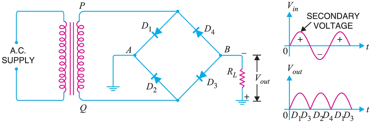
During the positive half-cycle of the secondary voltage, the end P of the secondary winding becomes positive, and end \(Q\) becomes negative. This makes diodes \(D1\) and \(D3\) forward-biased, while diodes \(D2\) and \(D4\) are reverse-biased. Therefore, only diodes \(D1\) and \(D3\) conduct. These two diodes will be in series through the load \(R_{L}\) as shown in Fig. 17. The conventional current flow is shown by dotted arrows. It may be seen that current flows from \(A\) to \(B\) through the load \(R_{L}\).
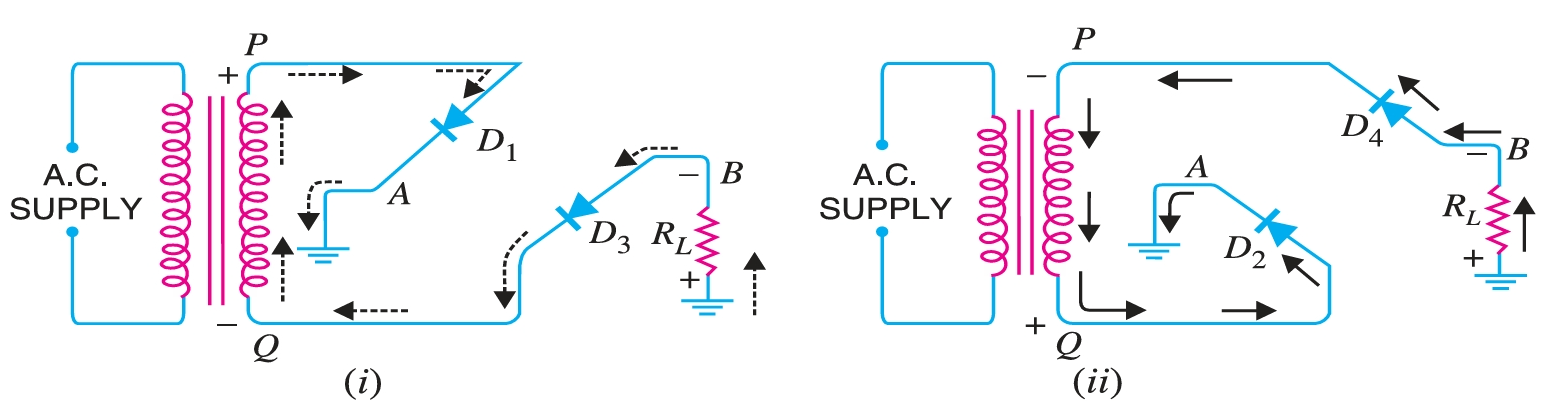
During the negative half-cycle of secondary voltage, end \(P\) becomes negative and end \(Q\) positive. This makes diodes \(D2\) and \(D4\) forward biased, whereas diodes \(D1\) and \(D3\) are reverse biased. Therefore, only diodes \(D2\) and \(D4\) conduct. These two diodes will be in series through the load \(R_{L}\) as shown in Fig. 18. The current flow is shown by the solid arrows. It may be seen that again current flows from \(A\) to \(B\) through the load, i.e., in the same direction as for the positive half-cycle. Therefore, d.c. output is obtained across load \(R_{L}\).
The peak inverse voltage (\(PIV\)) of each diode is equal to the maximum secondary voltage of the transformer. Suppose during the positive half cycle of the input a.c., end \(P\) of the secondary is positive and end \(Q\) negative. Under such conditions, diodes \(D1\) and \(D3\) are forward-biased while diodes \(D2\) and \(D4\) are reverse-biased. Since the diodes are considered ideal, diodes \(D1\) and \(D3\) can be replaced by wires.
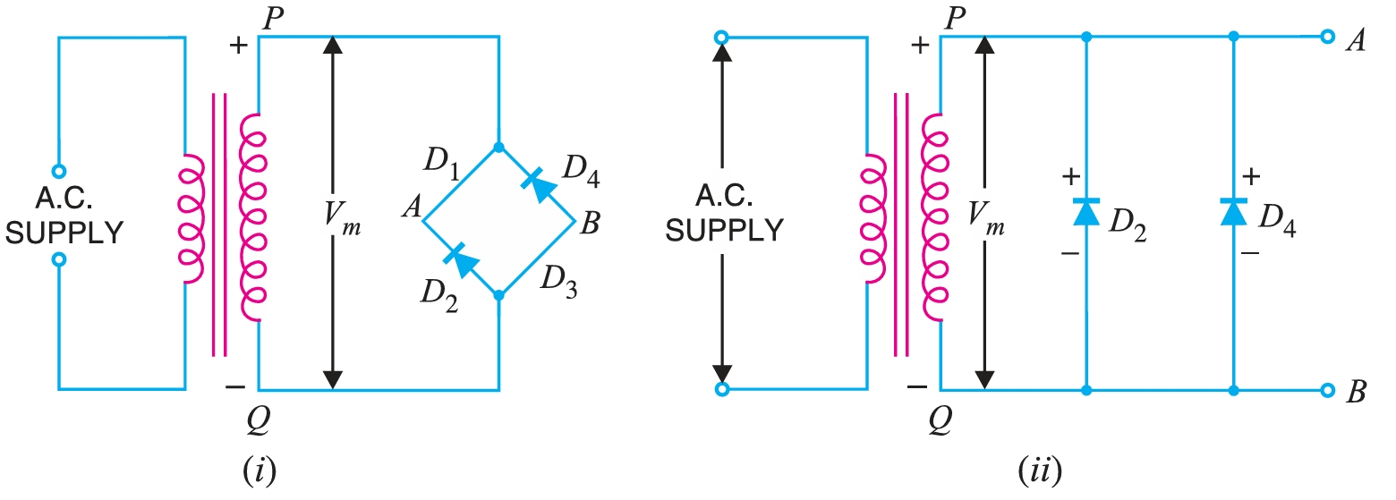
It is clear that two reverse-biased diodes (i.e., \(D2\) and \(D4\)) and the secondary of the transformer are in parallel. Hence \(PIV\) of each diode (\(D2\) and \(D4\)) is equal to the maximum voltage (\(V_{m}\)) across the secondary. Similarly, during the next half cycle, \(D2\) and \(D4\) are forward-biased, while \(D1\) and \(D3\) are reverse-biased. It is easy to see that reverse voltage across \(D1\) and \(D3\) is equal to \(V_{m}\). The output frequency of a full-wave rectifier is double the input frequency. A wave has a complete cycle when it repeats the same pattern. In Fig. 19, the input a.c. completes one cycle from 0° – 360°. However, the full-wave rectified wave completes 2 cycles in this period. Therefore, output frequency is twice the input frequency, i.e.
\[f_{out} = 2 f_{in}\]
Advantages
- (i) The need for a centre-tapped transformer is eliminated.
- (ii) The output is twice that of the centre-tap circuit for the same secondary voltage.
- (iii) The PIV is one-half that of the centre-tap circuit (for the same d.c. output).
Disadvantages
- (i) It requires four diodes.
- (ii) As during each half-cycle of a.c. input two diodes that conduct are in series; therefore, the voltage drop in the internal resistance of the rectifying unit will be twice as great as in the centre tap circuit. This is objectionable when the secondary voltage is small.
Efficiency of Full-Wave Rectifier
Let \(v = V_{m} \sin θ\) be the a.c. voltage to be rectified having a corresponding current, \(i = I_{m} \sin θ\). Let \(r_d\) and \(R_{L}\) be the diode resistance and load resistance, respectively. Obviously, the rectifier will conduct current through the load in the same direction for both half-cycles of input a.c. voltage. The instantaneous current \(i\) is given by :
- d.c. output power The output current is a pulsating direct current. Therefore, in order to find the d.c. power, the average current must be determined. \[I_{dc} = \frac{2I_{m}}{\pi}\] \[\therefore \text{d.c. power, } P_{dc} = I_{dc}^2 R_L = \left(\frac{2I_{m}}{\pi}\right)^2 R_L\]
- a.c. input power The current through the half wave rectifier circuit, \(I_{rms}\) is given as: \[I_{rms} = \sqrt{\frac{1}{2\pi} \int_0^{2\pi} i^2 ~d\theta}\] \[I_{rms} = \sqrt{\frac{1}{2\pi} \int_0^{2\pi} I_{m}^2 \sin^{2}\theta ~d\theta}\] \[I_{rms} = \sqrt{\frac{I_{m}^2}{2\pi} \int_0^{2\pi} \sin^{2}\theta ~d\theta}\] \[I_{rms} = \sqrt{\frac{I_{m}^2}{2\pi} \int_0^{2\pi} \sin^{2}\theta ~d\theta}\] \[I_{rms} = \sqrt{\frac{I_{m}^2}{2\pi} \int_0^{2\pi} \left[\frac{1 - \cos(2\theta)}{2}\right] ~d\theta}\] \[I_{rms} = \sqrt{\frac{I_{m}^2}{2\pi} \left[ \frac{\theta}{2} - \frac{1}{4}\sin(2\theta) \right]_0^{2\pi}}\] \[I_{rms} = \sqrt{\frac{I_{m}^2}{2\pi} \left[ \frac{2\pi}{2} - \frac{1}{4}\sin(4\pi) \right]}\] \[I_{rms} = \sqrt{\frac{I_{m}^2}{2\pi} [ \pi ]}\] \[I_{rms} = \sqrt{\frac{I_{m}^2}{2}}\] \[I_{rms} = \frac{I_{m}}{\sqrt{2}}\] The a.c. input power is given by: \[P_{ac} = I_{rms}^2 (r_d+R_L)\] For a full-wave rectified wave, we have, \[I_{rms}=\frac{I_m}{\sqrt{2}}\] \[\therefore \qquad P_{ac} = \left(\frac{I_m}{\sqrt{2}}\right)^2 (r_d+R_L)\]
- Full wave rectification efficiency \[\eta = \frac{P_{dc}}{P_{ac}} = \frac{\left(\frac{I_{m}}{\pi}\right)^2 R_L}{\left(\frac{I_m}{\sqrt{2}}\right)^2 (r_d+R_L)}\] \[\eta = \left(\frac{8}{\pi^2}\right)\times\frac{R_L}{(r_d+R_L)}\] \[\eta = 0.812\times\frac{R_L}{(r_d+R_L)} = \frac{0.812}{\left(\frac{R_L+r_d}{R_L}\right)} \] \[\eta = \frac{0.812}{\left(1+\frac{r_d}{R_L}\right)} \]
The efficiency will be maximum if \(r_d\) is negligible as compared to \(R_L\). \[\therefore \qquad \qquad \text{Maximum efficiency } = 81.2 ~\%\]
This is double the efficiency due to a half-wave rectifier. Therefore, a full-wave rectifier is twice as effective as a half-wave rectifier.
| S. No. | Particulars | Half-wave | Centre-tap | Bridge type |
|---|---|---|---|---|
| 1 | No. of diodes | \(1\) | \(2\) | \(4\) |
| 2 | Transformer necessary | no | yes | no |
| 3 | Max. efficiency | \(40.6 ~\%\) | \(81.2 ~\%\) | \(81.2 ~\%\) |
| 4 | Ripple factor | \(1.21\) | \(0.48\) | \(0.48\) |
| 5 | Output frequency | \(f_{in}\) | \(2f_{in}\) | \(2f_{in}\) |
| 6 | Peak inverse voltage | \(V_m\) | \(2V_m\) | \(V_m\) |
A comparison among the three rectifier circuits must be made with great care. Although the bridge circuit has some disadvantages, it is the best circuit from the viewpoint of overall performance. When the transformer cost is the main consideration in a rectifier assembly, we invariably use the bridge circuit. This is particularly true for large rectifiers, which have a low-voltage and a high-current rating.