Filter Circuits
A rectifier is required to produce pure d.c. supply for use at various places in the electronic circuits. However, the output of a rectifier has pulsating character i.e., it contains a.c. and d.c. components. The a.c. component is undesirable and must be kept away from the load. If such a d.c. is applied in an electronic circuit, it will produce a hum.
A filter circuit is used to do so, removing (or filtering out) the a.c. component and allows only the d.c. component to reach the load.
A filter circuit is a device that removes the a.c. component of the rectifier output, but allows the d.c. component to reach the load.
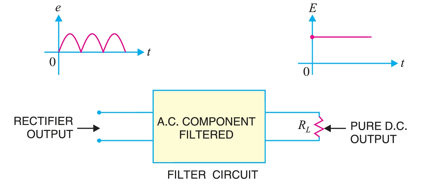
A filter circuit should be installed between the rectifier and the load, as shown in Fig. 1. A filter circuit is generally a combination of inductors (\(L\)) and capacitors (\(C\)). The filtering action of \(L\) and \(C\) depends upon the basic electrical principles. A capacitor passes a.c. readily, but does not pass d.c. at all. A capacitor offers infinite reactance to d.c.
For d.c., \(f = 0\).
\[X_C = \frac{1}{2\pi fC} = \frac{1}{2\pi\times 0 \times C} = \infty\]
Hence, a capacitor does not allow d.c. to pass through it.
On the other hand, an inductor opposes a.c. but allows d.c. to pass through it. The inductive reactance is given as:
\[X_L = 2\pi fL \]
For d.c., \(f = 0\) and, therefore, \(X_L = 0\). Hence inductor passes d.c. quite readily. For a.c., it offers opposition and drops a part of it.
It then becomes clear that a suitable network of \(L\) and \(C\) can effectively remove the a.c. component, allowing the d.c. component to reach the load.
Types of Filter Circuits
The most commonly used filter circuits are the capacitor filter, the choke input filter, the capacitor input filter (\(\pi\)-filter), and the \(\pi\)-filter. We shall discuss these filters in turn.
Capacitor filter.
Fig. 2 shows a typical capacitor filter circuit. It consists of a capacitor \(C\) placed in parallel with the load \(R_L\) across the rectifier output. The pulsating direct voltage of the rectifier is applied across the capacitor. As the rectifier voltage increases, it charges the capacitor and also supplies current to the load.
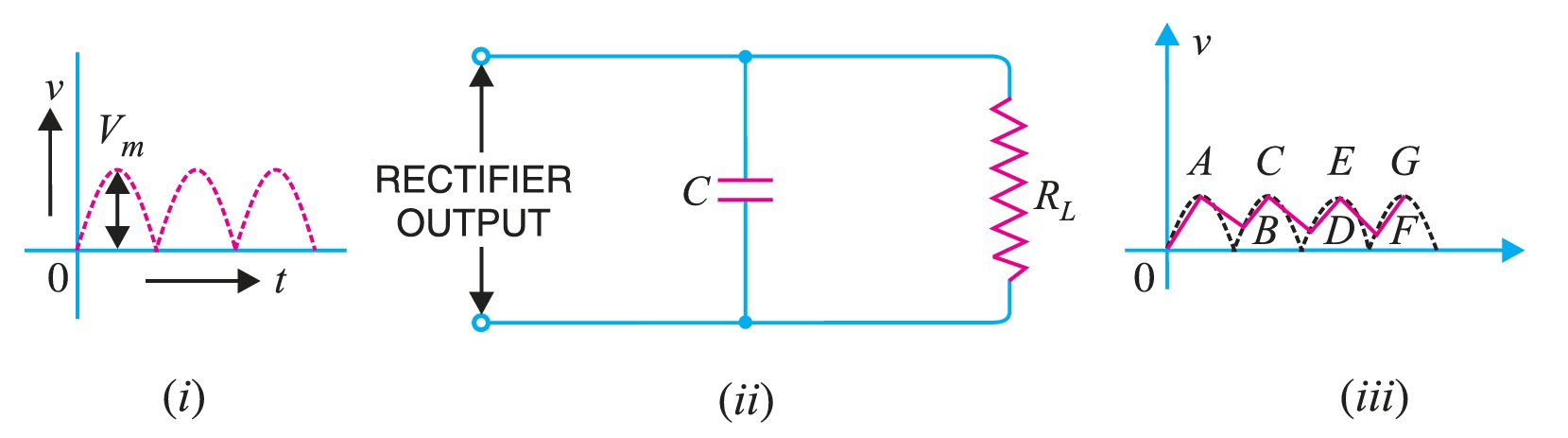
At the end of the quarter cycle [Point A in Fig. 2], the decrease. As this occurs, the capacitor discharges through the load, and the voltage across it (i.e., across a parallel combination of \(R-C\)) decreases as shown by the line \(AB\) in Fig 2. The voltage across the load will decrease only slightly, because the next voltage peak immediately follows and recharges the capacitor. This process is repeated, and the output voltage waveform becomes \(ABCDEFG\). It may be seen that very little ripple is left in the output. Moreover, the output voltage is higher as it remains substantially near the peak value of the rectifier output voltage. The capacitor filter circuit is extremely popular due to its low cost, small size, low weight, and good performance. For small load currents, this type of filter is preferred. It is commonly used in transistor radio battery eliminators.
Choke input filter
Fig. 3 shows a typical choke input filter circuit. It consists of a choke \(L\) connected in series with the rectifier output and a filter capacitor \(C\) across the load. Only a single filter section is shown, but several identical sections are often used to reduce the pulsations as effectively as possible. The pulsating output of the rectifier is applied across terminals \(1\) and \(2\) of the filter circuit.
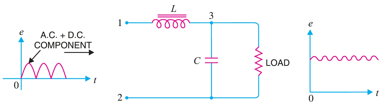
The pulsating output of the rectifier contains a.c. and d.c. components. The choke offers high opposition to the passage of a.c. component but negligible opposition to the d.c. component. The result is that most of the a.c. component appears across the choke while the whole of the d.c. The component passes through the choke on its way to the load. This results in the reduced pulsations at terminal \(3\)
At terminal \(3\), the rectifier output contains d.c. component and the remaining part of the a.c. A component that has managed to pass through the choke. Now, the low reactance of the filter capacitor bypasses the a.c. component but prevents the d.c. component to flow through it. Therefore, only d.c. component reaches the load. In this way, the filter circuit has removed the a.c. component. component from the rectifier output, allowing d.c. component to reach the load.
Capacitor input filter
Fig. 4 shows a typical capacitor-input filter, or \(\pi-\)filter. It consists of a filter capacitor \(C_1\) connected across the rectifier output, a choke \(L\) in series, and another filter capacitor \(C_2\) connected across the load.
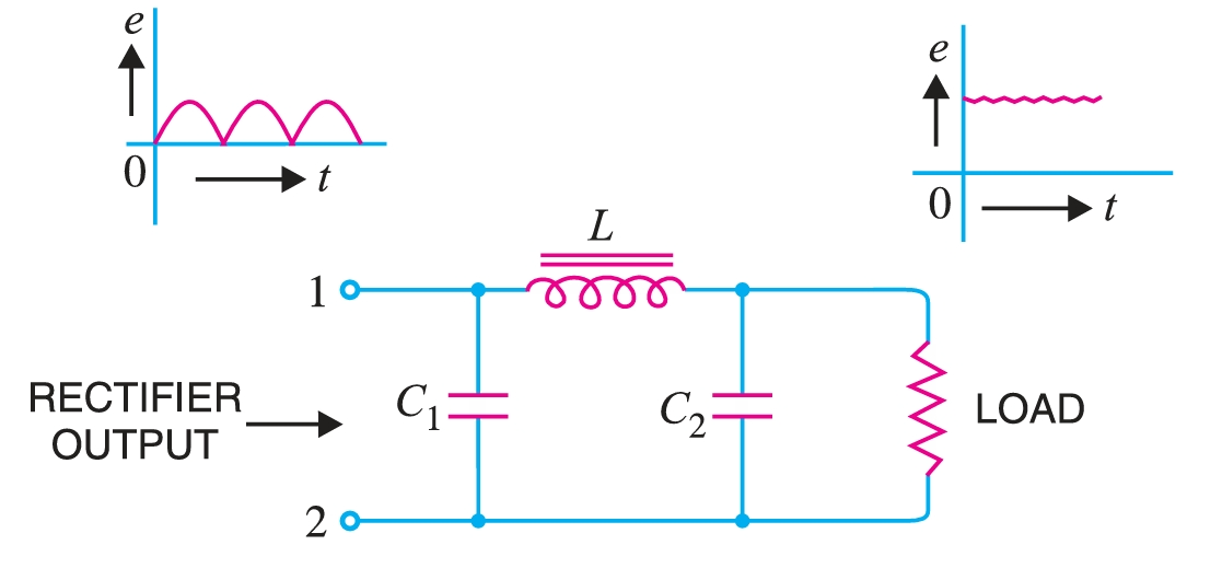
Only one filter section is shown, but several identical sections are often used to enhance smoothing. The pulsating output from the rectifier is applied across the input terminals (i.e., terminals \(1\) and \(2\)) of the filter. The filtering action of the three components, viz, \(C_1\), \(L\), and \(C_2\) of this filter, is described below :
- (a) The filter capacitor \(C_1\) offers low reactance to a.c. component of the rectifier output, while it offers infinite reactance to the d.c. component. Therefore, capacitor \(C_1\) bypasses an appreciable amount of a.c. component while the d.c. component continues its journey to the choke \(L\).
- (b) The choke \(L\) offers high reactance to the a.c. component, but it offers almost zero reactance to the d.c. component. Therefore, it allows the d.c. component to flow through it, while the *unbypassed a.c. component is blocked.
- (c) The filter capacitor \(C_2\) bypasses the a.c. The component that the choke has failed to block. Therefore, only d.c. component appears across the load, and that is what we desire.
