Mid-Point Biasing
When an amplifier circuit is so designed that the operating point \(Q\) lies at the centre of the d.c. load line, the amplifier is said to be midpoint biased. When the amplifier is mid-point biased, the \(Q\)-point provides values of \(I_{C}\) and \(V_{CE}\) that are one-half of their maximum possible values. Since the \(Q\)-point is centred on the load line,
\[I_{C} = \frac{1}{2} I _{C\text{max}} \]
\[ V_{CE} = \frac{V_{CC}}{2} \]
When a transistor is used as an amplifier, it is always designed for mid-point bias. The reason is that midpoint biasing allows op timum operation of the amplifier. In other words, midpoint biasing provides the largest possible output where the \(Q\) point is centred on the load line.
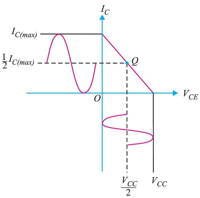
When an ac signal is applied to the base of the transistor, collector current and collector-emitter voltage will both vary around their \(Q\)-point values. Since the \(Q\)-point is centred, \(I_{C}\) and \(V_{CE}\) can both make the maximum possible transitions above and below their initial DC values. If the \(Q\)-point is located above the centre on the load line, the input may cause the transistor to saturate. As a result, a portion of the output wave will be clipped. Similarly, if the \(Q\) point lies below the mid-point on the load line, the input may cause the transistor to enter cut-off. This can also cause a portion of the output to be clipped. It follows that a midpoint-biased amplifier circuit provides the best possible ac operation.
