Operational Amplifier (OP-AMP)
Fig. 1 shows the block diagram of an operational amplifier (OP-amp). The input stage of an op amp is a differential stage, followed by additional gain stages and a class B push-pull emitter follower.
The important properties common to all operational amplifiers (OP-amps) are:
- An operational amplifier is a multistage amplifier. The input stage of an OP-amp is a differential amplifier stage.
- An inverting input and a noninverting input.
- A high input impedance (usually assumed infinite) at both inputs.
- A low output impedance \((\lt 200 \,\Omega)\).
- A large open-loop voltage gain, typically \(10^{5}\).
- The voltage gain remains constant over a wide frequency range.
- Very large CMRR \((\gt 90 \,\text{dB})\).
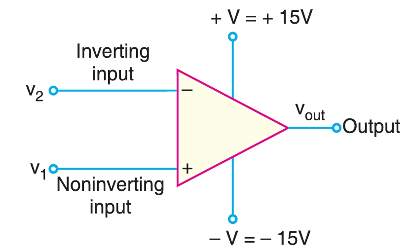
Fig. 2 shows the schematic symbol of an operational amplifier.
The basic operational amplifier has five terminals: two terminals for supply voltages \(+\text{V}\) and \(–\text{V}\); two input terminals (inverting input and noninverting input), and one output terminal.
The input terminals are marked \(+\) and \(–\). These are not polarity signs. The \(–\) sign indicates the inverting input while the \(+\) sign indicates the non-inverting input. A signal applied to the plus terminal will appear at the output in the same phase as at the input. A signal applied to the minus terminal will be shifted in phase by 180° at the output.
The voltages \(v_{1}\), \(v_{2}\) and \(v_{\text{out}}\) are node voltages. This means that they are always measured with respect to the ground. The differential input \(v_{\text{in}}\) is the difference of two node voltages \(v_{1}\) and \(v_{2}\). The ground in the symbol is not shown.
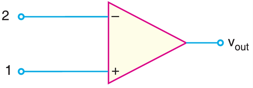
For the sake of simplicity, \(+ \,\text{V}\) and \(–\,\text{V}\) terminals are often omitted from the symbol as shown in Fig. 2. The two input leads are always shown on the symbol, regardless of whether both are used. In most cases, if only one input is required for an OP-amp circuit, the input not in use will be shown connected to ground. A single-input OP-amp is generally classified as either inverting or noninverting.
The OP-amp is produced as an integrated circuit \((IC)\). Because of the complexity of the internal circuitry of an OP-amp, the OP-amp symbol is used exclusively in circuit diagrams.
The output voltage from an OP-amp for a given pair of input voltages depends mainly on the factors, namely, the voltage gain, the polarity relationship between \(v_{1}\) and \(v_{2}\), and the values of supply voltages, \(+\text{V}\) and \(–\text{V}\).
Voltage gain
The maximum possible voltage gain from a given OP-amp is called open-loop voltage gain and is denoted by the symbol \(A_{OL}\). The value of \(A_{OL}\) for an OP-amp is generally greater than \(10000\). The term open-loop indicates a circuit condition where there is no feedback path from the output to the input of the OP-amp.
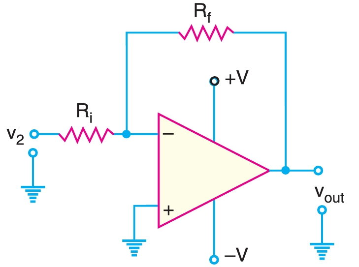
The OP-amps are almost always operated with negative feedback, i.e., a part of the output signal is fed back in phase opposition to the input. \(R_{\text{i}}\) is the input resistance, and \(R_{f}\) is the feedback resistor. Consequently, the voltage gain of the OP amplifier is reduced. When a feedback path is present, such as the \(R_{f}\) connection in Fig. 3, the resulting circuit gain is referred to as closed-loop voltage gain \((A_{CL})\).
The maximum voltage gain of the given OP-amp is \(A_{OL}\). Its value is generally greater than \(10000\). The actual gain \((A_{CL})\) of an OP-amp is reduced when a negative feedback path exists between the output and the input.
Polarity Relationship.
The polarity relationship between \(v_{1}\) and \(v_{2}\) will determine whether the OP-amp output voltage polarity is positive or negative. The differential input voltage \(v_{\text{in}}\) is the difference between the non-inverting input \((v_{1})\) and inverting input \((v_{2})\), i.e.,
\[v_{\text{in}}=v_{1}–v_{2}\]
When the result of this equation is positive, the OP-amp output voltage will be positive. When the result of this equation is negative, the output voltage will be negative.
Supply Voltages
The supply voltages for an OP-amp are normally equal in magnitude and opposite in sign. These supply voltages set the upper and lower limits of the output voltage of the OP-amp. These limits, known as saturation voltages, are generally given by;
\[+V_{\text{sat}}=+V_{\text{supply}}–2\text{V}\] \[–V_{\text{sat}}=–V_{\text{supply}}+2\text{V}\]
Although input terminals of an OP-amp are labeled as \(+\) and \(–\), this does not mean you have to apply positive voltages to the \(+\) terminal and negative voltages to the \(–\) terminal. Any voltage can be applied to either terminal. The true meaning of the input terminal labels (\(+\) and \(–\)) is that a positive voltage applied to the \(+\) terminal drives the output voltage towards \(+V\) of d.c. supply; a positive voltage applied to the \(–\) terminal drives the output voltage towards \(–V\) of d.c. supply.
A.C. Analysis
The basic OP-amp has two input terminals and one output terminal. The input terminals are labeled as + (noninverting input) and –(inverting input).
A signal applied to the non-inverting input \((+)\) produces an output voltage in phase with the input voltage. However, a signal applied to the inverting input \((–)\) will produce an output voltage that is 180° out of phase with the input signal.
Practical OP–amp
Fig. 4 shows the a.c. equivalent circuit of a practical OP-amp. The characteristics of a practical OP-amp are: very high voltage gain, very high input impedance, and very low output impedance. The input voltage \(v_{\text{in}}\) appears between the two input terminals, and the output voltage is \(A_{v}v_{\text{in}}\) taken through the output impedance \(Z_{\text{out}}\). The consequences of these properties of a practical OP–amp are:
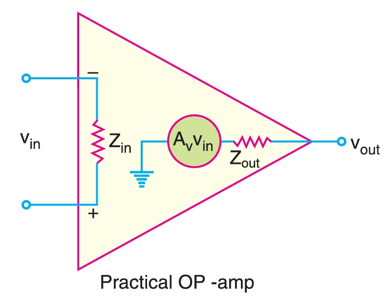
- Since the voltage gain \((A_{v})\) of a practical OP-amp is very high, an extremely small input voltage \((v_{\text{in}})\) will produce a large output voltage \((v_{\text{out}})\).
- Since the input impedance \((Z_{\text{in}})\) is very high, a practical OP-amp has a very small input current.
- Since the output impedance \((Z_{\text{out}})\) of a practical OP-amp is very low, it means that the output voltage is practically independent of the value of the load connected to the OP-amp.
Ideal OP-amp
Fig. 6 shows the a.c. equivalent circuit of an ideal OP-amp. The characteristics of an ideal OP-amp are: infinite voltage gain, infinite input impedance, and zero output impedance. The consequences of these properties of an ideal OP-amp are :
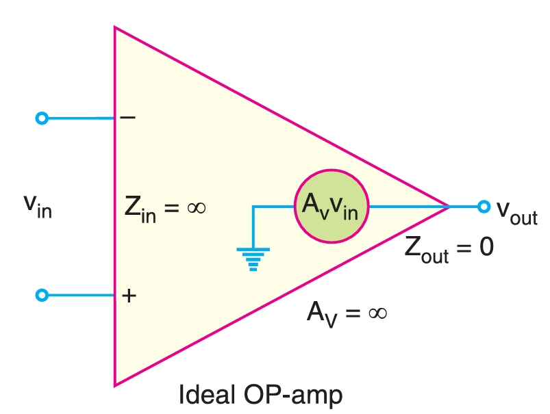
- Since the voltage gain \((A_{v})\) of an ideal OP-amp is infinite, it means that we can set \(v_{\text{in}} = 0\,\text{V}\).
- Since the input impedance \((Z_{\text{in}})\) is infinite, an ideal OP-amp has zero input current.
- Since the output impedance \((Z_{\text{out}})\) of an ideal OP-amp is zero, it means the output voltage does not depend on the value of the load connected to the OP-amp. The values of parameters of a practical OP-amp and an ideal OP-amp are tabulated as:
| Parameter | Practical OP-amp | Ideal OP-amp |
|---|---|---|
| \(Z_{\text{in}}\) | \(2 \,\text{M}\Omega\) | \(\rightarrow \infty\) |
| \(A_{v}\) | \(1 \times 10^{5}\) | \(\rightarrow \infty\) |
| \(Z_{\text{out}}\) | \(100 \,\Omega\) | \(0 \,\Omega\) |
Bandwidth
All electronic devices work only over a limited range of frequencies. This range of frequencies is called bandwidth. Every OP-amp has a bandwidth, i.e., the range of frequencies over which it will work properly. The bandwidth of an OP-amp depends upon the closed-loop gain of the OP-amp circuit. One important parameter is gain-bandwidth product (GBW). It is defined as under :
\[A_{CL} \times f_{2} = f_{\text{unity}} = \text{GBW} \]
where \(A_{CL}\) is closed-loop gain at frequency \(f_{2}\), \(f_{\text{unity}}\) is frequency at which the closed-loop gain is unity. The gain-bandwidth product of an OP-amp is constant. Since an OP-amp is capable of operating as a d.c. amplifier, its bandwidth is \((f_{2} – 0)\). The gain-bandwidth product of an OP-amp is an important parameter because it can be used to find :
- The maximum value of \(A_{CL}\) at a given value of \(f_{2}\).
- The value of \(f_{2}\) for a given value of \(A_{CL}\).
Slew Rate
The slew rate of an OP-amp is a measure of the rate of change of output voltage and is measured in volts per microsecond \((\text{V}/\mu s)\). The slew rate of \(0.5\,\text{V}/\mu s\) means that the output from the amplifier can change by \(0.5 \,\text{V}\,\) every \(\mu s\). Since frequency is a function of time, the slew rate can be used to determine the maximum operating frequency of the OP-amp as follows:
Maximum operating frequency, \(f_{\text{max}}\),
\[f_{\text{max}} = \frac{\text{Slew rate}}{2\pi V_{\text{peak}}}\]
Here, \(V_{\text{peak}}\) is the peak output voltage.
Frequency Response
The operating frequency significantly affects the operation of an OP-amp. The maximum operating frequency of an OP-amp is given by;
\[f_{\text{max}} = \frac{\text{Slew rate}}{2\pi V_{\text{peak}}}\]
Thus, the peak output voltage limits the maximum operating frequency. When the maximum operating frequency of an OP-amp is exceeded, the result is a distorted output waveform. Increasing the operating frequency of an OP-amp beyond a certain point will decrease the maximum output voltage swing, decrease the open-loop voltage gain, decrease the input impedance and increase the output impedance.
OP-Amp with Negative Feedback
An OP-amp is almost always operated with negative feedback, i.e., a part of the output is fed back in phase opposition to the input. The reason is that the open-loop voltage gain of an OP-amp is very high (usually greater than \(1,00,000\)). Therefore, an extremely small input voltage drives the OP-amp into its saturated output stage.
For example, assume \(v_{\text{in}} = 1\,\text{mV}\) and \(A_{OL} = 1,00,000\). Then,
\[v_{\text{out}} = A_{OL} v_{\text{in}} = (1,00,000) \times (1\,\text{ mV}) = 100 \,\text{V} \]
Since the output level of an OP-amp can never reach \(100 \,\text{V}\), it is driven deep into saturation and the device becomes non-linear. With negative feedback, the voltage gain (ACL) can be reduced and controlled so that OP-amp can function as a linear amplifier. In addition to providing a controlled and stable gain, negative feedback also controls the input and output impedances and the amplifier bandwidth. The table below shows the general effects of negative feedback on the performance of OP-amps.
| Voltage gain | Input Z | Output Z | Bandwidth | |
|---|---|---|---|---|
| Without negative feedback | AOL is too high for linear amplifier applications | Relatively high | Relatively low | Relatively narrow |
| With negative feedback | ACL is set by the feedback circuit to the desired value | Can be increased or reduced to a desired value, depending on the type of circuit | Can be reduced to a desired value | Significantly wider |