Teacher: Prof P. M. Sarun • NPHC206 • WINTER - 2025-2026 • Last updated:
Questions
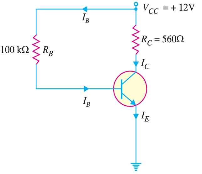
Determine the collector current \(I_{C}\) and collector-emitter voltage \(V_{CE}\). Neglect small base-emitter voltage. Given that \(\beta = 50\). If \(R_{B}\) in this circuit is changed to \(50 \,\text{k}\Omega\), find the new operating point.
Figure .
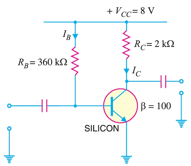
A silicon transistor with \(\beta = 100\) is biased by base resistor method. Draw the d.c. load line and determine the operating point. What is the stability factor?
Figure .
A germanium transistor is to be operated at zero signal \(I_{C} = 1 \,\text{mA}\). If the collector supply \(V_{CC} = 12 \, V\), what is the value of \(R_{B}\) in the base resistor method? Take \(\beta = 100\). If another transistor of the same batch with \(\beta = 50\) is used, what will be the new value of zero signal \(I_{C}\) for the same \(R_{B}\)?
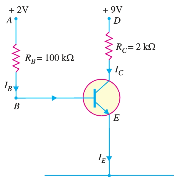
Calculate the values of three transistor currents in the circuit.
Figure .
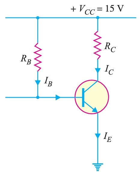
Design base resistor bias circuit for a \(CE\) amplifier such that operating point is \(V_{CE} = 8\, \text{V}\) and \(I_{C} = 2 \, \text{mA}\). You are supplied with a fixed \(15 \, V\) d.c. supply and a silicon transistor with \(\beta = 100\). Take base-emitter voltage \(V_{BE} = 0.6 \, \text{V}\). Calculate also the value of load resistance that would be employed.
Figure .
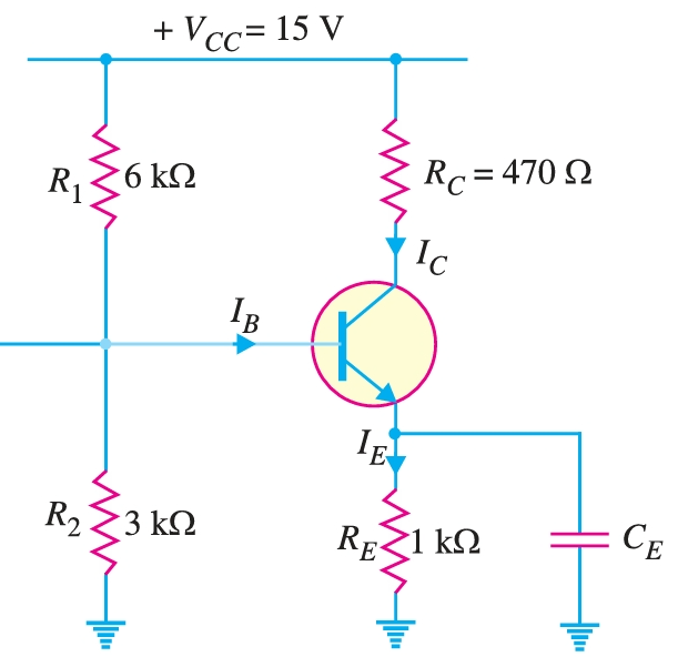
A fixed bias circuit in figure is subjected to an increase in temperature from 25 °C to 75 °C. If \(\beta = 100\) at 25 °C and 150 at 75 °C, determine the percentage change in \(Q\)-point values (\(V_{CE}\) and \(I_{C}\)) over this temperature range. Neglect anychange in \(V_{BE}\) and the effects of any leakage current.
Figure .
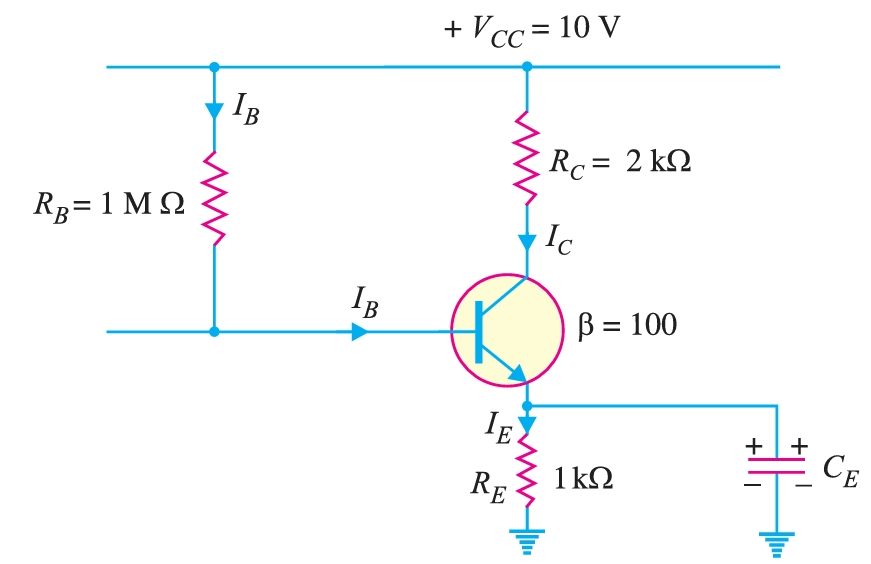
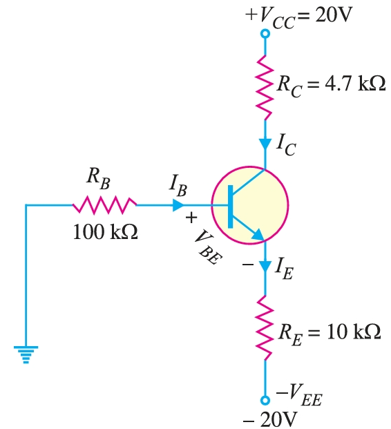
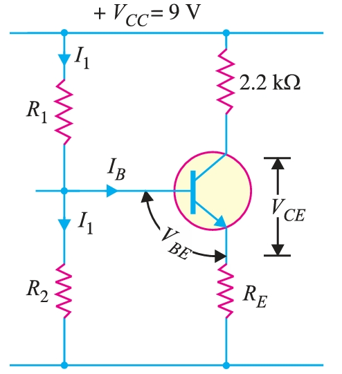
For the emitter bias circuit, find \(I_{E}\), \(I_{C}\), \(V_{C}\) and \(V_{CE}\) for \(\beta = 85\) and \(V_{BE} = 0.7\, \text{V}\)
Figure .
Determine how much the \(Q\)-point of question \(8\), will change over a temperature range where \(\beta\) increases from \(85\) to \(100\) and \(V_{BE}\) decreases from \(0.7 \,\text{V}\) to \(0.6 \,\text{V}\).
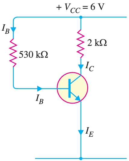
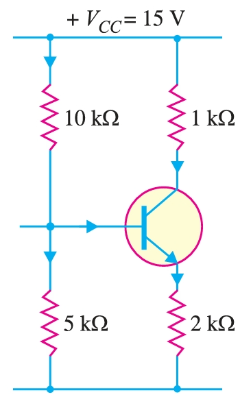
Draw the d.c. load line and determine the operating point. Assume the transistor to be of silicon.
Figure .
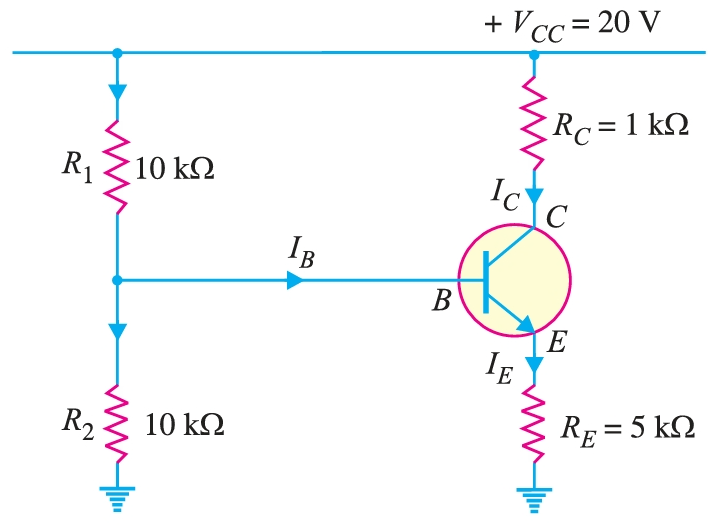
Determine the operating point of the circuit shown in the previous question by using Thevenin's theorem.
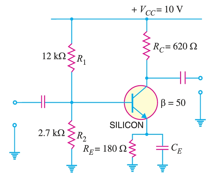
A transistor uses potential divider method of biasing. \(R_{1} = 50 \, \text{k}\Omega\), \(R_{2} = 10 \, \text{k}\Omega\) and \(R_{E} = 1\, \text{k}\Omega\). If \(V_{CC} = 12 \,\text{V}\), find : (i) the value of \(I_{C}\) ; given \(V_{BE} = 0.1 \,\text{V}\), (ii) the value of \(I_{C}\) ; given \(V_{BE} = 0.3\,\text{V}\).
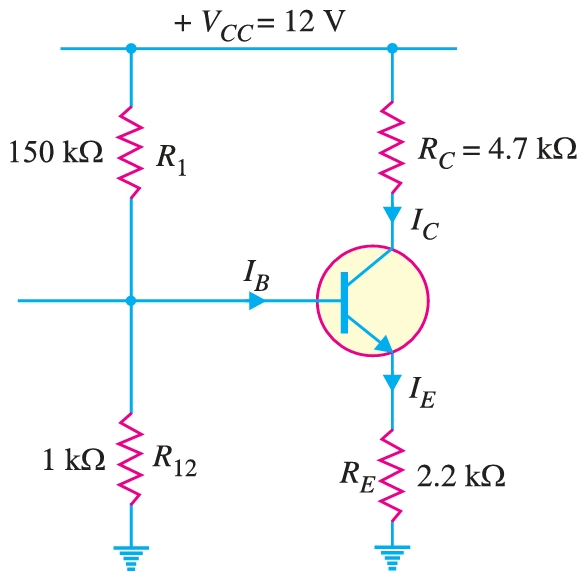
Calculate the emitter current in the voltage divider circuit shown in figure. Also find the value of \(V_{CE}\) and collector potential \(V_{C}\).
Figure .
For the circuit shown in Fig., find the operating point. What is the stability factor of the circuit? Given that \(\beta = 50\) and \(V_{BE} = 0.7 \,\text{V}\).
Figure .
The circuit shown in Fig. uses silicon transistor having \(\beta = 100\). Find the operating point and stability factor.
Figure .
In the circuit shown in Fig., the operating point is chosen such that \(I_{C} = 2 \,\text{mA}\), \(V_{CE} = 3\,\text{V}\). If \(R_{C} = 2.2 \,\text{k}\Omega\), \(V_{CC} = 9 \,\text{V}\) and \(\beta = 50\), determine the values of \(R_{1}\), \(R_{2}\) and \(R_{E}\). Take \(V_{BE} = 0.3 \,\text{V}\) and \(I_{1} = 10 \,I_{B}\)
Figure .
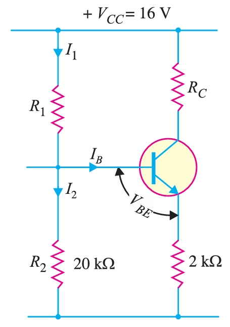
An \(npn\) transistor circuit has \(\alpha = 0.985\) and \(V_{BE} = 0.3\,\text{V}\). If \(V_{CC} = 16\,\text{V}\), calculate \(R_{1}\) and \(R_{C}\) to place \(Q\)-point at \(I_{C} = 2\, \text{mA}\), \(V_{CE} = 6 \,\text{V}\).
Figure .
Determine whether or not the circuit shown in Fig. is midpoint biased.
Figure .
Determine whether or not the circuit shown in Fig. is midpoint biased.
Figure .