Sequential Circuit:
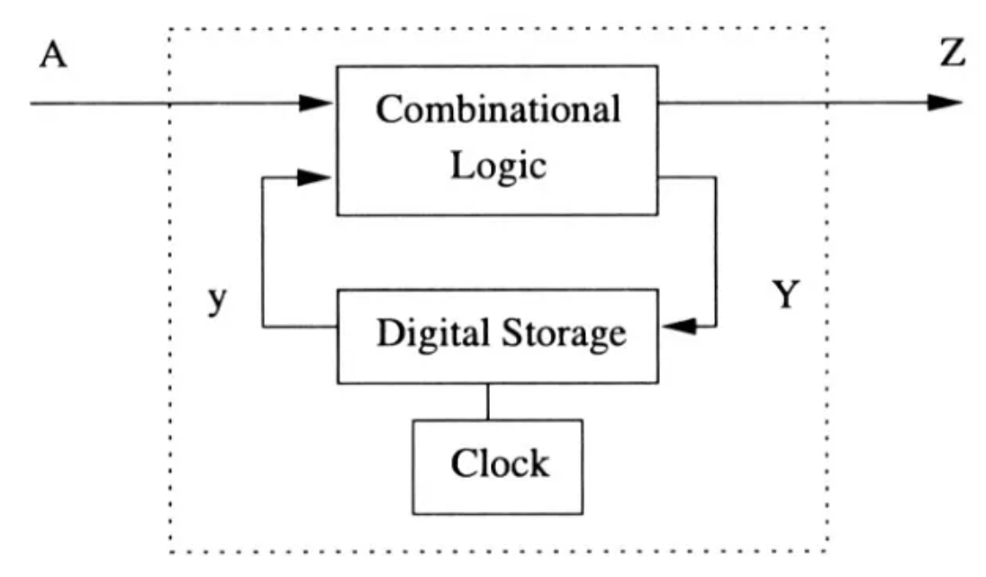
The sequential circuits are dynamic digital circuits that incorporate memory elements to store information and generate outputs based on current inputs and internal states. Their behavior depends on past inputs and states, and they rely on clock signals for coordinated transitions. This sets them apart from combinational circuits, which produce outputs solely based on current inputs without any memory or clock dependencies. In other words, a sequential circuit is a type of digital circuit that stores and processes information over time using memory elements like flip-flops and registers. Unlike combinational circuits that solely depend on the current inputs to produce outputs, sequential circuits have memory elements that allow them to consider past inputs and internal states to determine their outputs. These circuits play a crucial role in various digital systems, ranging from simple devices like counters and timers to complex systems like microprocessors and memory units.
Characteristics of Sequential Circuits:
- Memory Elements: The fundamental building blocks of sequential circuits are memory elements, typically flip-flops or registers. These elements store binary values (0 or 1) and retain them until explicitly changed by external inputs or internal logic.
- Feedback Loops: Sequential circuits often incorporate feedback loops, allowing the output to influence subsequent inputs. This feedback mechanism gives these circuits the ability to maintain internal states and generate outputs based on current inputs and previous states.
- Clock Signal: Sequential circuits usually operate in synchrony with a clock signal. The clock ensures that the memory elements change their states only at specific instants, preventing unintended transitions and ensuring predictable behavior.
- State Transitions: The transition from one internal state to another occurs during clock cycles. This transition is governed by the logic that determines how the current state, inputs, and the clock signal influence the next state and outputs.
Types of Sequential Circuits:
- Synchronous Sequential Circuits: These circuits have a clock signal that synchronizes the changes in memory elements. The outputs are updated only at specific clock edges, leading to predictable and coordinated behavior.
- Asynchronous Sequential Circuits: In contrast to synchronous circuits, asynchronous circuits do not rely on a clock signal. Instead, they change states whenever the internal conditions dictate. These circuits are harder to design and analyze due to their unpredictable timing characteristics.
Difference between Sequential and Combinational Circuits:
- Memory: The most significant difference lies in the presence of memory. Sequential circuits utilize memory elements to store information, allowing them to consider past inputs and states. Combinational circuits, on the other hand, do not have memory and produce outputs solely based on current inputs.
- Behavior: Sequential circuits exhibit behavior that depends not only on the current inputs but also on previous inputs and internal states. Combinational circuits, however, generate outputs directly from the current inputs, devoid of any notion of history.
- Clock Signal: Sequential circuits require a clock signal to coordinate state transitions and output updates. Combinational circuits do not rely on clock signals and provide immediate outputs based on input changes.
- Feedback: Feedback loops are inherent in sequential circuits, enabling them to retain states and create dynamic behavior. Combinational circuits lack feedback loops and are inherently static in nature.
Clock for Flip-Flops:
Introduction:
The clock signal is a fundamental component in digital circuits, particularly in sequential logic circuits like flip-flops. It plays a crucial role in synchronizing the operation of these circuits and ensuring the reliable transfer of data. This article delves into the intricacies of clock signals in flip-flops, discussing their importance, characteristics, and various types of flip-flops that utilize clocks.
Importance of Clock Signals:
In digital circuits, flip-flops are building blocks for storing and transferring binary information. They are used to implement memory elements, registers, counters, and more. The clock signal dictates when the flip-flop's state can change. Without proper clocking, flip-flops could transition unpredictably, leading to erroneous behavior in the circuit.
Characteristics of Clock Signals:
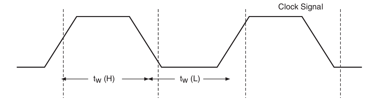
- Period and Frequency: The clock signal has a period (T) representing the time between successive rising (or falling) edges. Frequency (f) is the reciprocal of the period and indicates the number of clock cycles per second (measured in Hertz, Hz).
- Duty Cycle: The duty cycle is the ratio of time the clock signal is high (or low) to the total period. It affects the overall behavior and performance of the flip-flop circuit.
- Skew: Skew refers to the timing difference between multiple clock signals in a system. Skew can lead to synchronization issues and metastability problems in flip-flop circuits.
- Rise and Fall Times: Rise time is the time taken for the clock signal to transition from low to high, while fall time is the reverse. Fast rise/fall times are essential for accurate clocking.
Clocking Strategies for Flip-Flops:
- Synchronous Clocking: In synchronous clocking, flip-flop state changes are synchronized to the clock signal's rising (or falling) edge. This ensures precise and predictable operation.
- Asynchronous Clocking: Asynchronous clocking refers to flip-flop operation that is not synchronized with a clock signal. This approach can lead to metastability issues and is generally avoided in most designs.
- Edge-Triggered Flip-Flops: Edge-triggered flip-flops change their state only at a specific edge of the clock signal (usually rising or falling). This reduces the likelihood of glitches and facilitates precise timing control.
- Level-Sensitive Flip-Flops: Unlike edge-triggered flip-flops, level-sensitive flip-flops change state continuously as long as the clock signal remains at a certain level. These are less common due to their susceptibility to glitches.
Clock Issues:
- Clock Skew and Delay: Clock skew is a timing discrepancy that occurs when clock signals take different paths through a circuit, resulting in varying arrival times. Delay elements can be introduced to compensate for skew and ensure synchronous operation.
- Metastability and Setup/Hold Time: Metastability occurs when a flip-flop's inputs are at an unstable state during a clock edge transition. It can lead to incorrect outputs. Proper setup and hold times (time before and after the clock edge) must be maintained to prevent metastability.
Clock Signal Considerations:
- Clock Signal Quality: Clock signals must have clean transitions, minimal noise, and appropriate voltage levels to ensure reliable operation of flip-flops.
- Clock Gating: Clock gating involves controlling the clock signal's path to flip-flops to reduce power consumption and improve efficiency.
- Clock Enable: A clock enable signal can be used to control when the clock signal is allowed to reach the flip-flop, enabling power savings.
Edge Triggering:
Edge triggering is a fundamental concept in digital electronics and signal processing that plays a crucial role in shaping the behavior of digital systems. It involves detecting and responding to transitions in input signals, specifically at the rising or falling edges. This technique is employed in various domains, including digital circuits, microcontrollers, communication systems, and more. Understanding the intricacies of edge triggering is essential for engineers and developers to design efficient and reliable digital systems. In this exploration, we delve into the significance, principles, types, applications, and challenges associated with edge triggering.
Significance of Edge Triggering:
Edge triggering serves as a pivotal mechanism in digital systems for initiating actions based on signal transitions. In contrast to level triggering, which responds to the continuous state of a signal, edge triggering focuses on the changes between signal levels. This technique allows systems to react to specific instances and provides precise timing control, contributing to improved synchronization and reduced power consumption.
Principles of Edge Triggering:
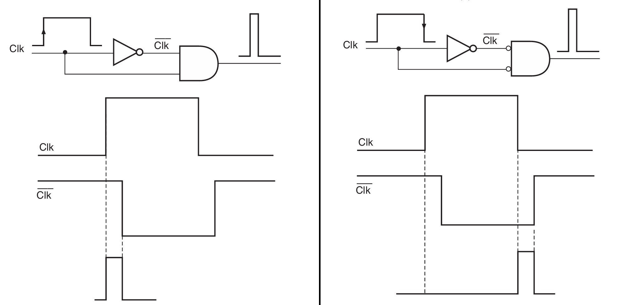
Edge triggering relies on detecting the transition between two voltage levels, commonly known as the rising edge (transition from low to high voltage) and the falling edge (transition from high to low voltage). These transitions occur at specific points in time and can be identified using various circuit elements, such as flip-flops, Schmitt triggers, and comparators.
Types of Edge Triggering:
Positive Edge Triggering (Rising Edge Triggering): This type of edge triggering responds to the transition from low to high voltage. It is commonly used in scenarios where actions need to be initiated when the signal becomes active or goes from an idle state to an active state.
Negative Edge Triggering (Falling Edge Triggering): Negative edge triggering is characterized by detecting the transition from high to low voltage. It is used when actions should be triggered as the signal transitions from an active state to an idle state.
Applications of Edge Triggering:
- Flip-Flops and Registers: Edge-triggered flip-flops are fundamental building blocks in digital circuits and memory elements. They store and synchronize data based on rising or falling edge transitions, allowing for precise data capture and control.
- Microcontrollers and Processors: Microcontrollers utilize edge triggering to respond to external events, such as button presses or sensor readings. By using edge-triggered interrupts, microcontrollers can efficiently handle real-time events.
- Communication Systems: In digital communication protocols like I2C and SPI, edge triggering ensures accurate data synchronization between devices. Edge-triggered signals help devices interpret the beginning and end of data bits.
- Clock Generation: Edge-triggered signals are often used to generate clock signals in digital systems. Clock generators utilize these transitions to produce synchronized timing signals that control the sequential execution of operations.
- Sensor Interfaces: Sensors that provide digital outputs rely on edge triggering to communicate changes in the sensed environment. This is evident in applications such as motion detection and environmental monitoring.