Demultiplexers
A demultiplexer performs the reverse process of multiplexer; it receives the information on a single line and steers to several output lines. Demultiplexer can also be called the Data Distributor as it can transmit the same data to the different lines. It transmits the data to \(2^N\) output lines, for which the select terminals of \(N\) bits are required. For example, to transmit the single data to four output lines (1:4 DMUX), select terminals of two bits are required; similarly for 1:8 DMUX select terminals of 3 bits are required and so on. The functional block diagrams of 1:4 DMUX and 1:8 DMUX are shown in figures.
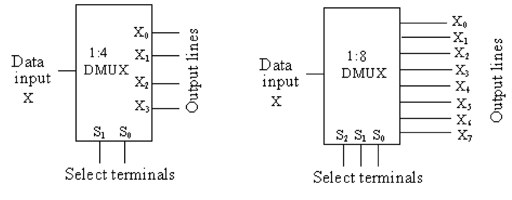
In a 1:4 DMUX, let \(X\) is the data input which is to be steered to 4 output lines \(X_0\), \(X_1\), \(X_2\), \(X_3\); the select terminals are (S_1),(S_0).
- If \(S_{1}\)\(S_{0}\) = \(00\) , the input data \(X\) will be go to the output \(X_0\).
- If \(S_{1}\)\(S_{0}\) = \(01\) , the input data \(X\) will be go to the output \(X_1\).
- If \(S_{1}\)\(S_{0}\) = \(10\) , the input data \(X\) will be go to the output \(X_2\).
- If \(S_{1}\)\(S_{0}\) = \(11\) , the input data \(X\) will be go to the output \(X_3\).
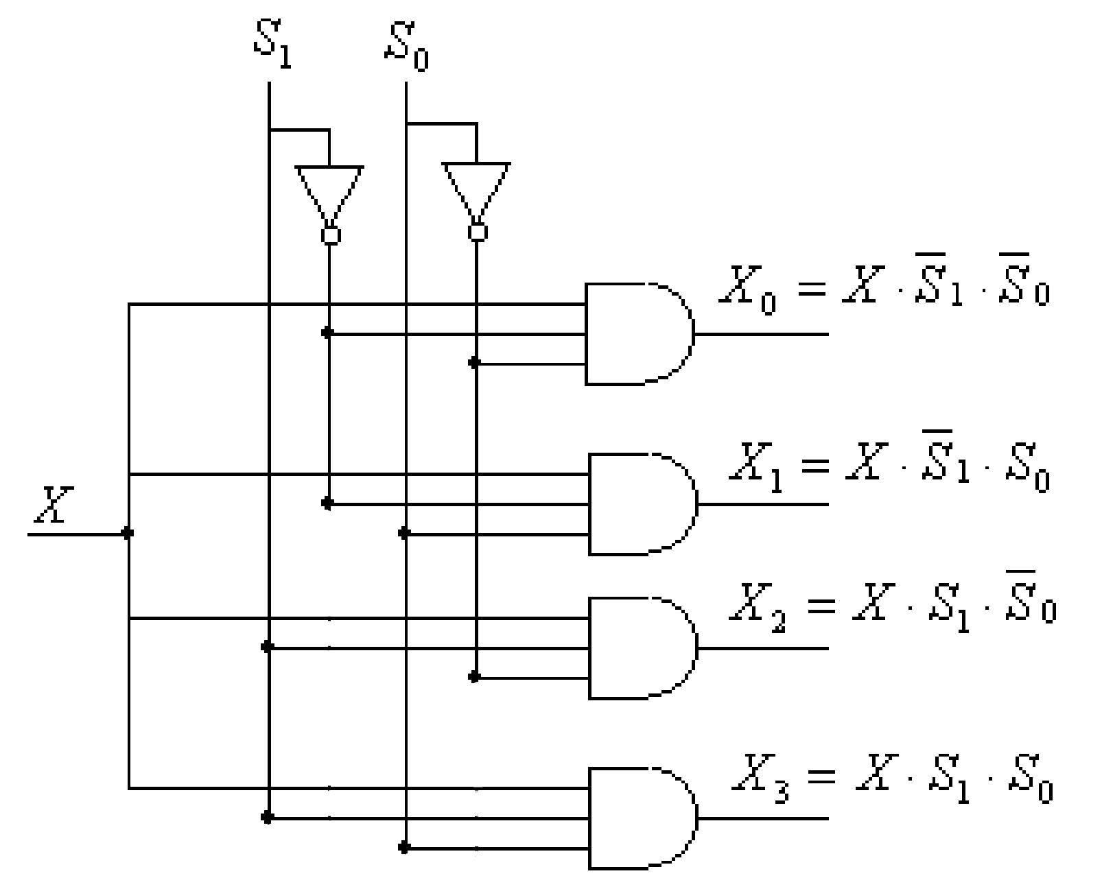
The Boolean expressions for \(X_0\), \(X_1\), \(X_2\), \(X_3\) are given by:
\[X_0 = X.\overline{S_1}.\overline{S_0}\] \[X_1 = X.\overline{S_1}.S_0\] \[X_2 = X.S_1.\overline{S_0}\] \[X_3 = X.S_1.S_0 \]The implementation of these functions (or 1:4 DMUX) can be done as shown in figure.