Counters
A counter is probably one of the most useful and versatile subsystems in a digital system. A counter driven by a clock can be used to count the number of clock cycles. Since the clock pulses occur at known intervals, the counter can be used as an instrument for measuring time and therefore period or frequency. There are basically two different types of counters-synchronous and asynchronous.
Counters such as these are called serial, or asynchronous where each flip-flop is triggered by the previous flip-flop, and thus the counter has a cumulative settling time. Synchronous counter are those where, every flip-flop is triggered by the clock (in synchronism), and thus settling time is simply equal to the delay time of a single flip-flop. The increase in speed is usually obtained at the price of increased hardware.
All of these counters progress one count at a time in a strict binary progression, and they all have a modulus given by \(2^n\), where \(n\) indicates the number of flip-flops. Such counters are said to have a "natural count" of 2". In general, in an arrangement of \(n\) flip-flops, the clock input to the nth flip-flop comes from the output of the \((n−1)^{th}\) flip-flop for \(n > 1\).
A mod-2 counter consists of a single flip-flop; a mod-4 counter requires two flip-flops, and it counts through four discrete states. Three flip-flops form a mod-8 counter, while four flip-flops form a mod-16 counter. Thus we can construct counters that have a natural count of \(2\), \(4\), \(8\), \(16\), \(32\), and so on by using the proper number of flip-flops
Excitation Table
The table which shows the inputs of the flip-flop for all the possible transition at the output is knows as the excitation table of that flip-flop.Truth table of SR Flip-flop
| \(S_{n}\) | \(R_{n}\) | \(Q_{n+1}\) |
|---|---|---|
| 0 | 0 | \(Q_{n}\) |
| 0 | 1 | 0 |
| 1 | 0 | 1 |
| 1 | 1 | (?) |
Excitation table of SR Flip-flop
| \(Q_{n}\) | \(Q_{n+1}\) | \(S_{n}\) | \(R_{n}\) |
|---|---|---|---|
| 0 | 0 | 0 | X |
| 0 | 1 | 1 | 0 |
| 1 | 0 | 0 | 1 |
| 1 | 1 | X | 0 |
Truth table of JK Flip-flop
| \(J_{n}\) | \(K_{n}\) | \(Q_{n+1}\) |
|---|---|---|
| 0 | 0 | \(Q_{n}\) |
| 0 | 1 | 0 |
| 1 | 0 | 1 |
| 1 | 1 | \(\overline{Q_{n}}\) |
Excitation table of JK Flip-flop
| \(Q_{n}\) | \(Q_{n+1}\) | \(J_{n}\) | \(K_{n}\) |
|---|---|---|---|
| 0 | 0 | 0 | X |
| 0 | 1 | 1 | X |
| 1 | 0 | X | 1 |
| 1 | 1 | X | 0 |
Truth table of T Flip-flop
| \(T_{n}\) | \(Q_{n+1}\) |
|---|---|
| 0 | \(Q_{n}\) |
| 1 | \(\overline{Q_{n}}\) |
Excitation table of T Flip-flop
| \(Q_{n}\) | \(Q_{n+1}\) | \(T_{n}\) |
|---|---|---|
| 0 | 0 | 0 |
| 0 | 1 | 1 |
| 1 | 0 | 1 |
| 1 | 1 | 0 |
Truth table of D Flip-flop
| \(D_{n}\) | \(Q_{n+1}\) |
|---|---|
| 0 | 0 |
| 1 | 1 |
Excitation table of D Flip-flop
| \(Q_{n}\) | \(Q_{n+1}\) | \(D_{n}\) |
|---|---|---|
| 0 | 0 | 0 |
| 0 | 1 | 1 |
| 1 | 0 | 0 |
| 1 | 1 | 1 |
Asynchronous Counters
Ripple counter
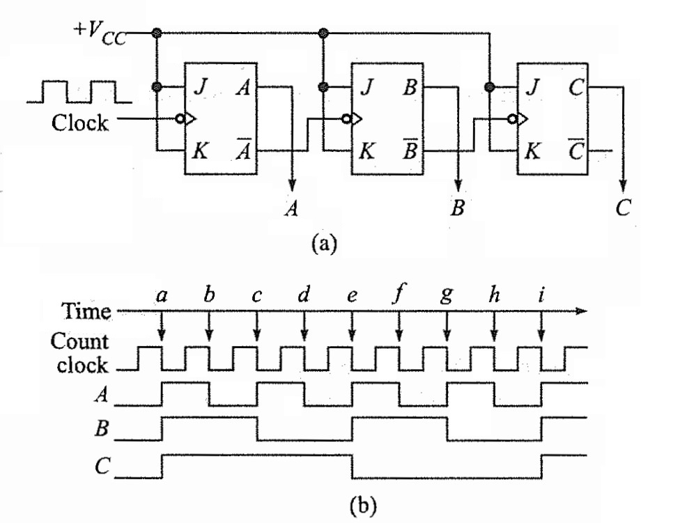
A ripple counter is a cascaded arrangement of flip-flops where the output of one flip-flop drives the clock input of the following flip-flop. The number of flip-flops in the cascaded arrangement depends upon the number of different logic states that it goes through before it repeats the sequence, a parameter known as the modulus of the counter.
In a ripple counter, also called an asynchronous counter or a serial counter, the clock input is applied only to the first flip-flop, also called the input flip-flop, in the cascaded arrangement. The clock input to any subsequent flip-flop comes from the output of its immediately preceding flip-flop.

Down Counter
Up Down Counter
Cyclic Shift Registers
In a regular shift register, a given number can be shifted to the left or right when a shift pulse is applied. Bits shifted out one end of the register may be lost. However, in a cyclic shift register, bits shifted out one end are shifted back in the other end. The cyclic shift registers also known as shift register counters are constructed by modifying serial in serial out (SISO) shift registers. There are two following types of cyclic shift registers:
- Ring Counter
- Johnson Counter or Twisted Ring Counter
These cyclic shift registers will be discussed in the following sections.
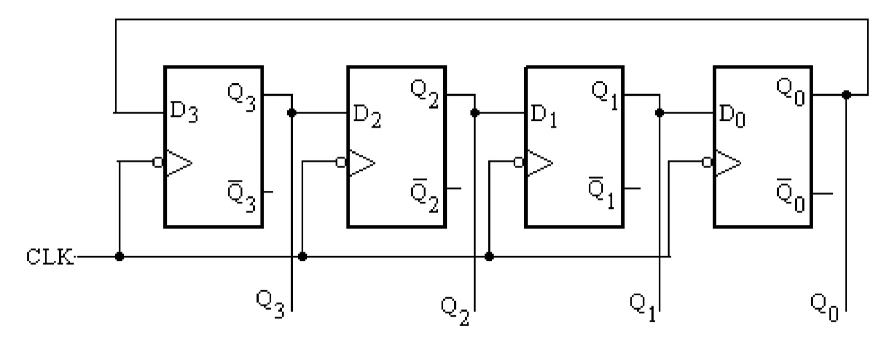
Ring Counter:
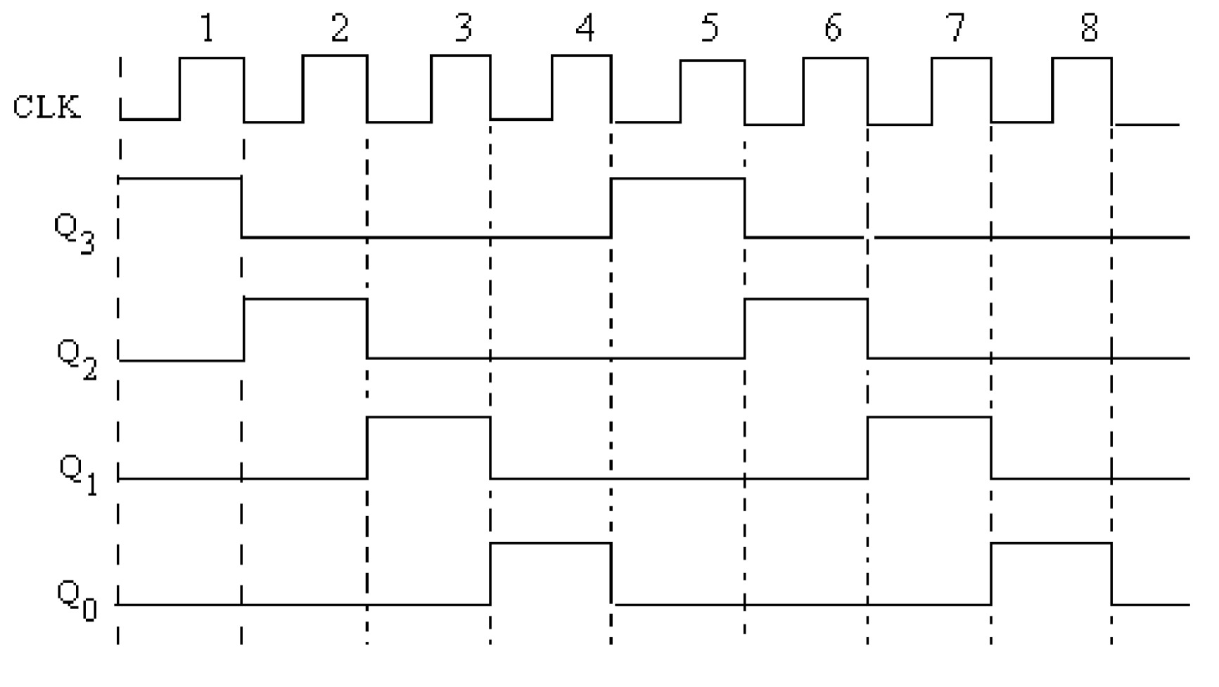
The ring counter can be obtained from a serial in serial out (SISO) shift register by connecting the Q0 output of the last flip-flop to the D input of the first flip-flop. The ring counter, constructed using the D flip-flops is shown in figure
| Clock | \(Q_{3}\) | \(Q_{2}\) | \(Q_{1}\) | \(Q_{0}\) |
|---|---|---|---|---|
| Zero | 1 | 0 | 0 | 0 |
| One | 0 | 1 | 0 | 0 |
| Two | 0 | 0 | 1 | 0 |
| Three | 0 | 0 | 0 | 1 |
| Four | 1 | 0 | 0 | 0 |
Johnson Counter:
The basic difference between the Johnson counter and ring counter is that in the Johnson counter the complement of the output of the last flip flop is connected back to the D input of the first flip flop rather than the output itself. This feedback arrangement produces a unique sequence of states. The four bit Johnson counter has a total of 8 states. In general, an n stage Johnson counter will produce a modulus of 2n, (n will also be the number of stages of the counter).
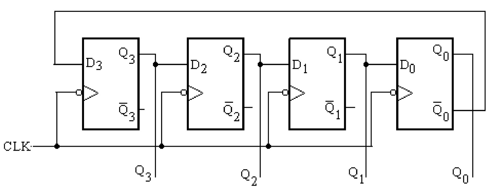
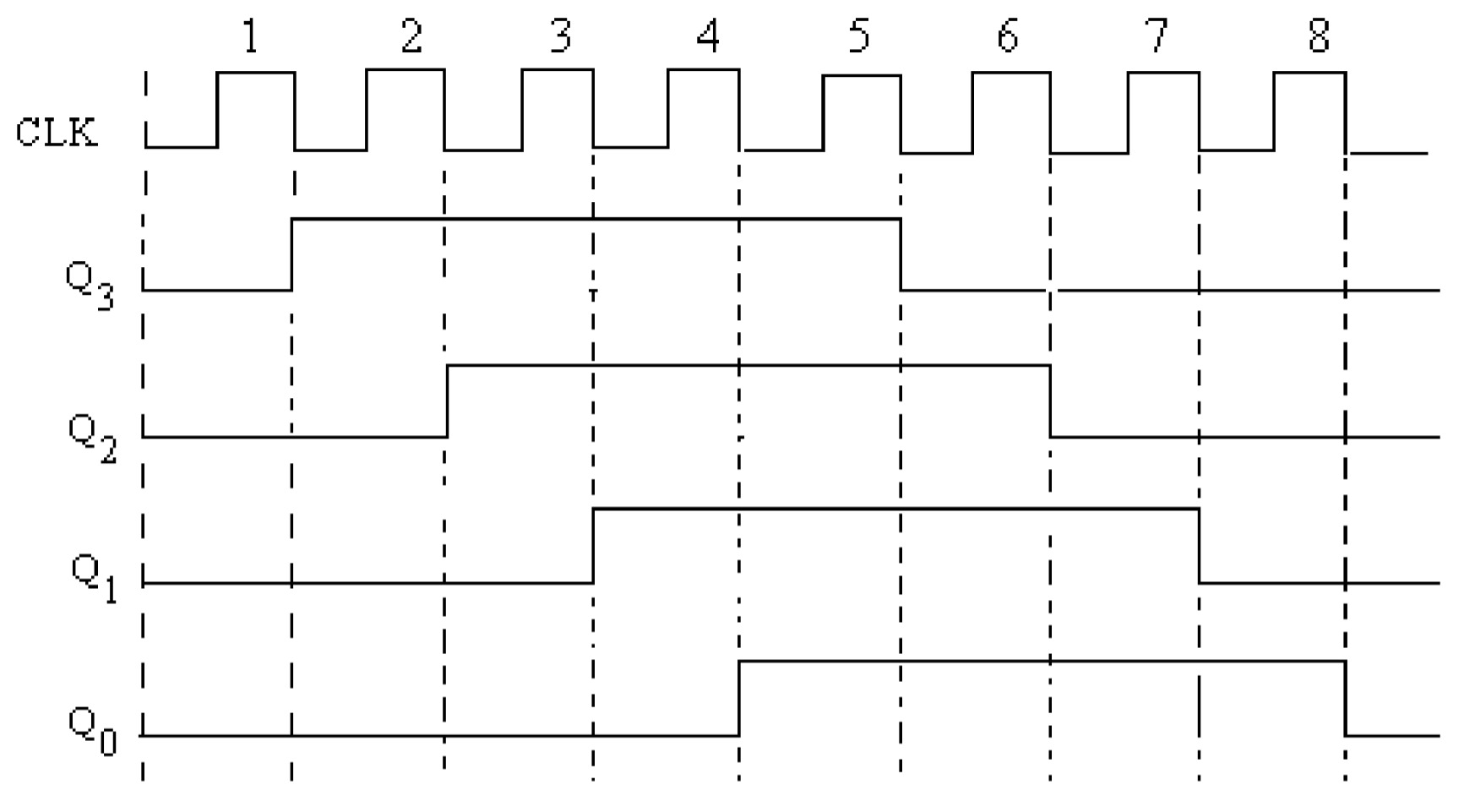
| Clock | \(Q_{3}\) | \(Q_{2}\) | \(Q_{1}\) | \(Q_{0}\) |
|---|---|---|---|---|
| Zero | 0 | 0 | 0 | 0 |
| One | 1 | 0 | 0 | 0 |
| Two | 1 | 1 | 0 | 0 |
| Three | 1 | 1 | 1 | 0 |
| Four | 1 | 1 | 1 | 1 |
| Five | 0 | 0 | 0 | 0 |
| Six | 1 | 0 | 0 | 1 |
Limitations of Ring counter and Johnson counter:
The flip-flop has two stable states. The \(n\) flip-flop are capable of counting \(2^n\) clock pulses. But the \(n\)-bit ring counter counts only \(n\) clock pulses and the Johnson counter counts only \(2n\) clock pulses. these counter cannot make efficient use of the flip-flops. The ripple counter overcomes this limitations.
Decoding Gates


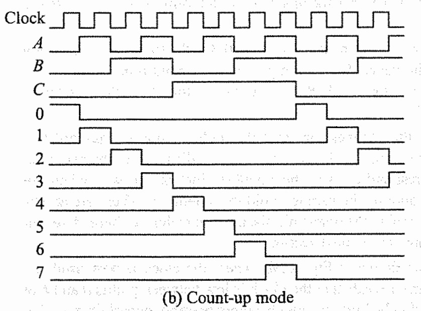
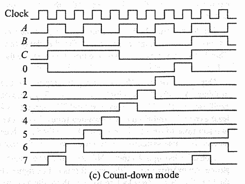
Synchronous counters

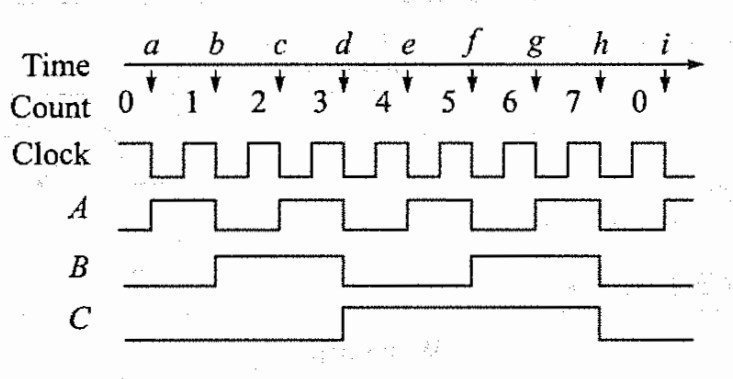
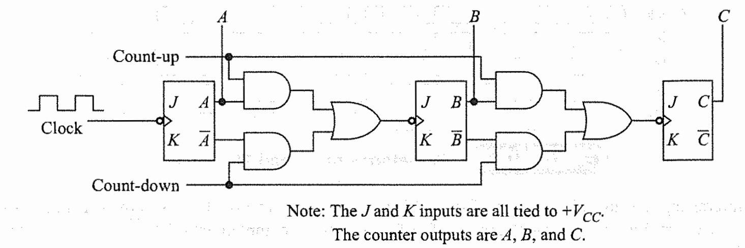
Up Down synchronous counter
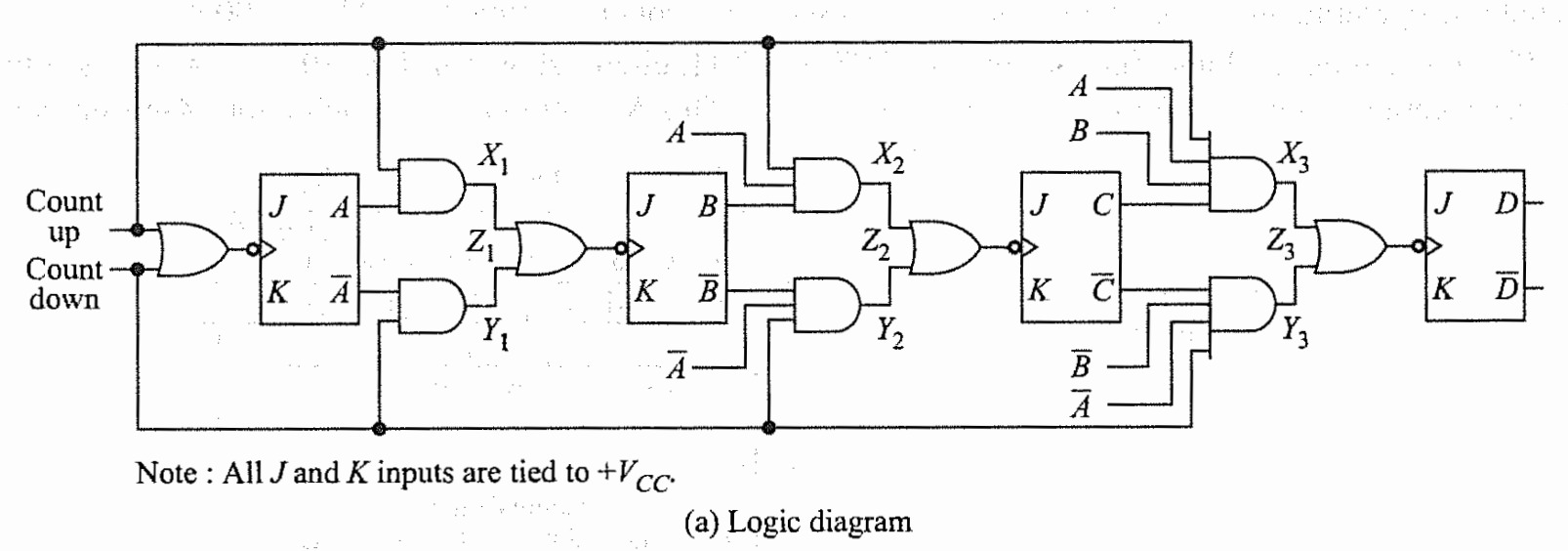


Parallel Up-down counter

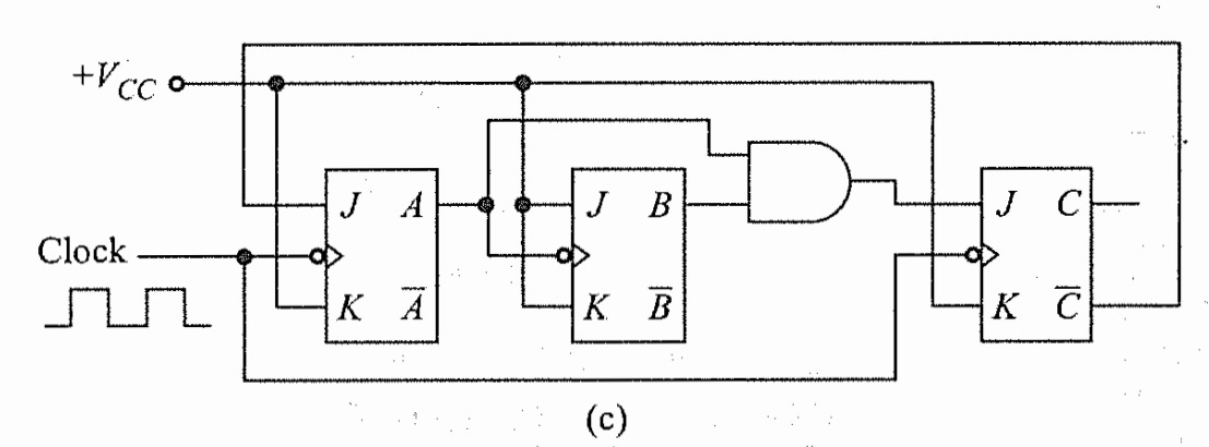
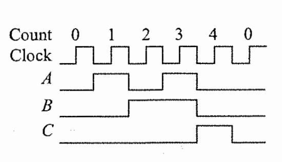
Mod-3 binary counter

Decade Counter


Truth table of Decade Counter
| D | C | B | A | Count |
|---|---|---|---|---|
| 0 | 0 | 0 | 0 | 0 |
| 0 | 0 | 0 | 1 | 1 |
| 0 | 0 | 1 | 0 | 2 |
| 0 | 0 | 1 | 1 | 3 |
| 0 | 1 | 0 | 0 | 4 |
| 0 | 1 | 0 | 1 | 5 |
| 0 | 1 | 1 | 0 | 6 |
| 0 | 1 | 1 | 1 | 7 |
| 1 | 0 | 0 | 0 | 8 |
| 1 | 0 | 0 | 1 | 9 |
| 0 | 0 | 0 | 0 | 0 |

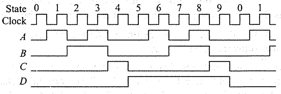
Truth table of (Mod-5 × 2) Decade Counter
| D | C | B | A | Count |
|---|---|---|---|---|
| 0 | 0 | 0 | 0 | 0 |
| 0 | 0 | 0 | 1 | 1 |
| 0 | 0 | 1 | 0 | 2 |
| 0 | 0 | 1 | 1 | 3 |
| 0 | 1 | 0 | 0 | 4 |
| 1 | 0 | 0 | 0 | 5 |
| 1 | 0 | 0 | 1 | 6 |
| 1 | 0 | 1 | 0 | 7 |
| 1 | 0 | 1 | 1 | 8 |
| 1 | 1 | 0 | 0 | 9 |
| 0 | 0 | 0 | 0 | 0 |
Sequence Generator
The logic circuit that generates a defined sequence of \(0\) and \(1\) in synchronism with the clock is known as a sequence generator. The output of the combinational circuit is a function of the output of the shift register. The output of the combinational circuit is applied as input to the shift register.
The steps to design the sequence generator are listed below:
- Determine the minimum number of flip-flops required by the equation \(S \leq 2^N-1\)
- Prepare the truth table of the \(N\)-bit shift register. The defined sequence is listed under \(Q_{N-1}\), and \(Y\) is the past input of the \(N-1\) flip-flop.
- Check for the repeated states in the truth table. Increase the number of flip-flops (\(N\)) to \(N+1\) if one or more repeated states are present and follow step 2 again.
- Draw and simplify the \(K\)-map for the output \(Y\).
- Draw the combinational logic circuit based on the simplified boolean equation for \(Y\).
Example: Design a sequence generator for the sequence \(1101011\).
Step 1: The length of the sequence is \(S=7\), and the minimum number of flip-flops required is \(N\).
\[S \leq 2^N-1\] \[7 \leq 2^N-1\] \[N=3\]Step 2: Truth table of 3-bit shift register for the sequence \(1101011\).
| \(Y\) | \(Q_2\) | \(Q_1\) | \(Q_0\) |
|---|---|---|---|
| 1 | 1 | 1 | 1 |
| 0 | 1 | 1 | 1 |
| 1 | 0 | 1 | 1 |
| 0 | 1 | 0 | 1 |
| 1 | 0 | 1 | 0 |
| 1 | 1 | 0 | 1 |
| 1 | 1 | 1 | 0 |
Truth table of \(4\)-bit shift register for the sequence \(1101011\) because of the repated states of \(111\) and \(101\).
| \(Y\) | \(Q_3\) | \(Q_2\) | \(Q_1\) | \(Q_0\) |
|---|---|---|---|---|
| 1 | 1 | 1 | 1 | 0 |
| 0 | 1 | 1 | 1 | 1 |
| 1 | 0 | 1 | 1 | 1 |
| 0 | 1 | 0 | 1 | 1 |
| 1 | 0 | 1 | 0 | 1 |
| 1 | 1 | 0 | 1 | 0 |
| 1 | 1 | 1 | 0 | 1 |
Step 3: Simplification of \(K\)-map
\[Y=\overline{Q_3}+\overline{Q_1}+\overline{Q_0}\]Step 4: Logic diagram to generate the defined sequence of \(1101011\).