Answer key
Ans. \(1 \)
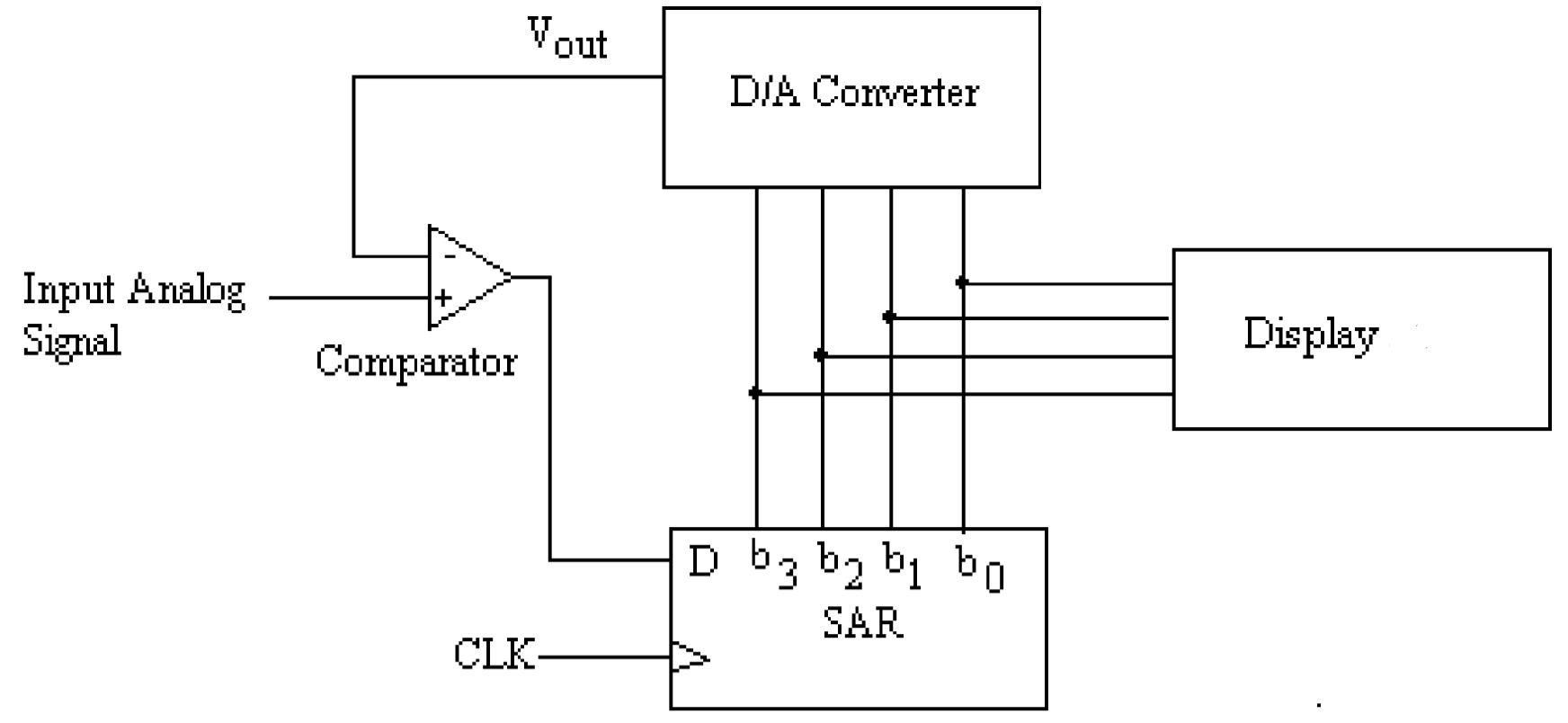
Working of Successive approximation A/D converter - (6 marks)
Write the Successive approximation method
Neat diagram - (4 marks)
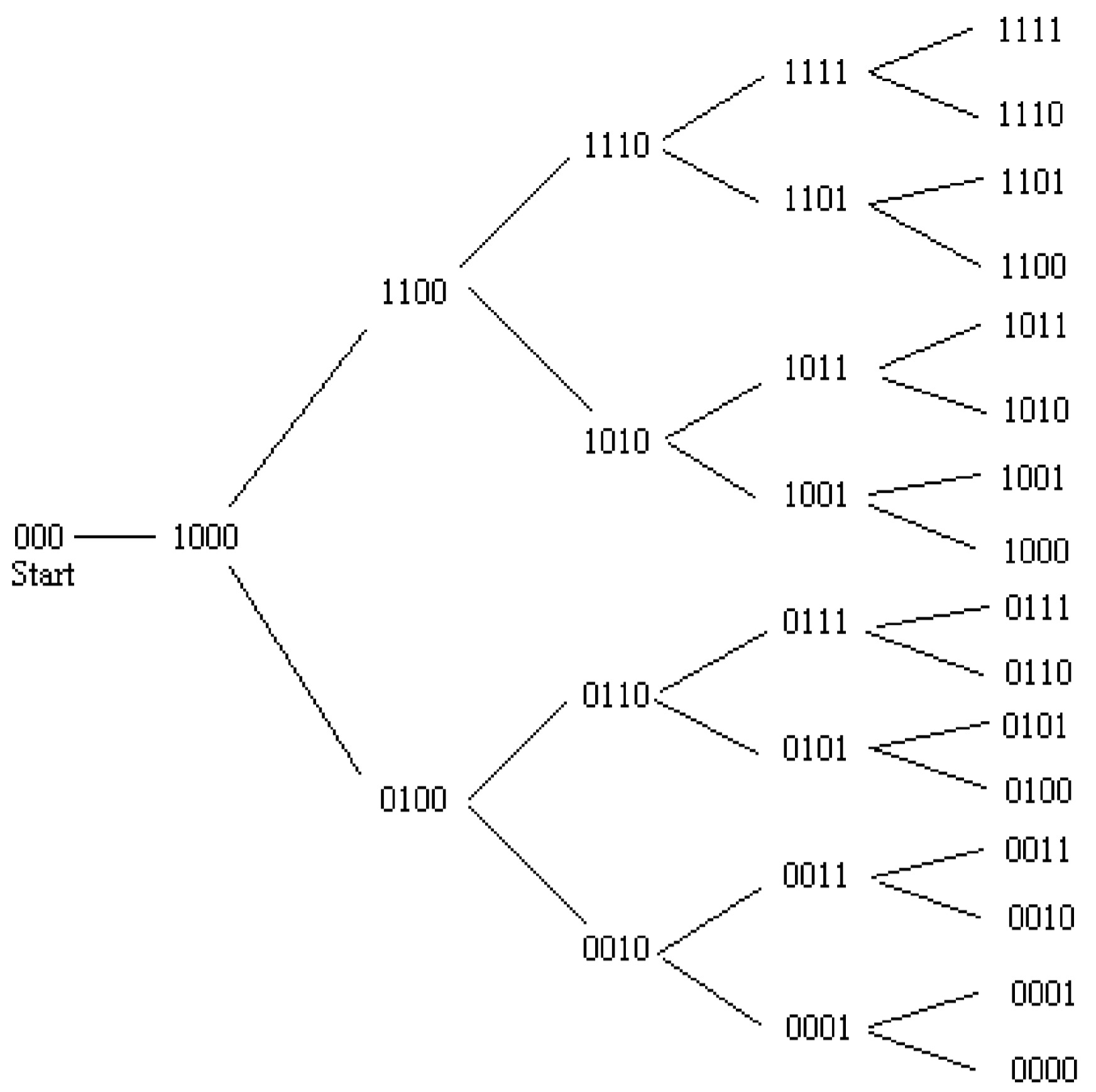
Flow chart showing the process of the Successive approximation method - (3 marks)
Ans. \(2 \)
Obtain the No. of \(D\) flip-flops required for sequence \(101101100\) - (1 marks)<
The length of the sequence, \(S = 9\)
\[S \leq 2^{N}-1\] \[9 \leq 2^{N}-1\] \[2^{N} \geq 10\] \[N = 4\]
Prepare the excitation table for generating the sequence (\101101100\) - (4 marks)
| Y | \(Q_{3}\) | \(Q_{2}\) | \(Q_{1}\) | \(Q_{0}\) | Repeat |
|---|---|---|---|---|---|
| 0 | 1 | 0 | 0 | 1 | Unique |
| 1 | 0 | 1 | 0 | 0 | Unique |
| 1 | 1 | 0 | 1 | 0 | Unique |
| 0 | 1 | 1 | 0 | 1 | R1 |
| 1 | 0 | 1 | 1 | 0 | R2 |
| 1 | 1 | 0 | 1 | 1 | Unique |
| 0 | 1 | 1 | 0 | 1 | R1 |
| 0 | 0 | 1 | 1 | 0 | R2 |
| 1 | 0 | 0 | 1 | 1 | Unique |
Since, there are two duplicates in the excitation table, \(N=5\) flip-flop is added. The new excitation table is given as:
| Y | \(Q_{4}\) | \(Q_{3}\) | \(Q_{2}\) | \(Q_{1}\) | \(Q_{0}\) | Repeat |
|---|---|---|---|---|---|---|
| 0 | 1 | 0 | 0 | 1 | 1 | Unique |
| 1 | 0 | 1 | 0 | 0 | 1 | Unique |
| 1 | 1 | 0 | 1 | 0 | 0 | Unique |
| 0 | 1 | 1 | 0 | 1 | 0 | Unique |
| 1 | 0 | 1 | 1 | 0 | 1 | R2 |
| 1 | 1 | 0 | 1 | 1 | 0 | Unique |
| 0 | 1 | 1 | 0 | 1 | 1 | Unique |
| 0 | 0 | 1 | 1 | 0 | 1 | R2 |
| 1 | 0 | 0 | 1 | 1 | 0 | Unique |
Since, there are one duplicates in the excitation table, \(N=6\) flip-flop is added. The new excitation table is given as:
| Y | \(Q_{5}\) | \(Q_{4}\) | \(Q_{3}\) | \(Q_{2}\) | \(Q_{1}\) | \(Q_{0}\) | Repeat |
|---|---|---|---|---|---|---|---|
| 0 | 1 | 0 | 0 | 1 | 1 | 0 | Unique |
| 1 | 0 | 1 | 0 | 0 | 1 | 1 | Unique |
| 1 | 1 | 0 | 1 | 0 | 0 | 1 | Unique |
| 0 | 1 | 1 | 0 | 1 | 0 | 0 | Unique |
| 1 | 0 | 1 | 1 | 0 | 1 | 0 | Unique |
| 1 | 1 | 0 | 1 | 1 | 0 | 1 | Unique |
| 0 | 1 | 1 | 0 | 1 | 1 | 0 | Unique |
| 0 | 0 | 1 | 1 | 0 | 1 | 1 | Unique |
| 1 | 0 | 0 | 1 | 1 | 0 | 1 | Unique |
Then the Boolean expression of the excitation table is given as
\[Y = \overline{Q_{5}}Q_{4}\overline{Q_{3}}~\overline{Q_{2}}Q_{1}Q_{0} + Q_{5}\overline{Q_{4}}Q_{3}\overline{Q_{2}}~\overline{Q_{1}}Q_{0} + \overline{Q_{5}}Q_{4}Q_{3}\overline{Q_{2}}Q_{1}\overline{Q_{0}} \] \[~+~Q_{5}\overline{Q_{4}}Q_{3}Q_{2}\overline{Q_{1}}Q_{0} + \overline{Q_{5}}~\overline{Q_{4}}Q_{3}Q_{2}\overline{Q_{1}}Q_{0}\]
Determine the Minimal Combinational circuit required for sequence \(101101100\) - (3 marks)
Converting \(Q_{5}=A\), \(Q_{4}=B\), \(Q_{3}=C\), \(Q_{2}=D\), \(Q_{1}=E\), \(Q_{0}=F\), the equation is written as,
\[Y = \overline{A}B\overline{C}~\overline{D}EF + A\overline{B}C\overline{D}~\overline{E}F + \overline{A}BC\overline{D}E\overline{F} + A\overline{B}CD\overline{E}F + \overline{A}~\overline{B}CD\overline{E}F\] \[Y=\overline{A}B\overline{D}E(\overline{C}F+C\overline{F})+(A\overline{B}C\overline{D} + A\overline{B}CD + \overline{A}~\overline{B}CD)\overline{E}F\] \[Y=\overline{A}B\overline{D}E(\overline{C}F+C\overline{F})+(A\overline{B}C\overline{D} + [~A + \overline{A}~]\overline{B}CD)\overline{E}F\] \[Y=\overline{A}B\overline{D}E(\overline{C}F+C\overline{F})+\overline{B}C(A\overline{D} + D)\overline{E}F\] \[Y=\overline{A}B\overline{D}E(\overline{C}F+C\overline{F})+\overline{B}C(A+D)(\overline{D} + D)\overline{E}F\] \[Y=\overline{A}B\overline{D}E(\overline{C}F+C\overline{F})+(A+D)\overline{B}C\overline{E}F\]
Final Solution:
\[Y=\overline{Q_{5}}Q_{4}\overline{Q_{2}}Q_{1}(\overline{Q_{3}}Q_{0}+Q_{3}\overline{Q_{0}})+(Q_{5}+Q_{2})\overline{Q_{4}}Q_{3}\overline{Q_{1}}Q_{0}\]
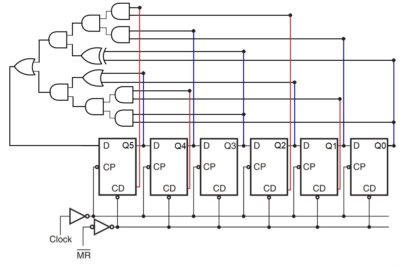
Draw the Circuit of the sequence generator - (4 marks)
Ans. \(3 \)
(a) \((+32)_{10} - (-64)_{10}\) - (4 marks)
\[(+32)_{10} = (00100000)_{2}\] \[(−64)_{10} = (11000000)_{2}\]
The \(2'\)s complement of \((−64)_{10} = (01000000)_{2}\)
\((+32)_{10} - (-64)_{10}\) is determined by adding the \(2'\)s complement of \((−64)_{10}\) to \((+32)_{10}\).
Therefore,
      00100000
    + 01000000
      --------
      01100000
      --------
The decimal equivalent of \((01100000)_{2}\) is \(+96\).
Verification using decimal numbers:
\[ +32 − (−64) = +96\]
(b) \((4F.B)_{16} - (29.A)_{16}\) - (5 marks)
\[(4F.B)_{16} = (01001111.1011)_{2}\]
The \(2'\)s complement of \((01001111.1011)_{2} = (01001111.1011)_{2}\)
\[(29.A)_{16} = (00101001.1010)_{2}\]
The \(2'\)s complement of \((00101001.1010)_{2}= (11010110.0110)_{2}\)
\((4F.B)_{16} - (29.A)_{16}\) is given by
      01001111.1011
    + 11010110.0110
      -------------
      00100110.0001
      -------------
The final carry discarded. Since the result is a positive number, \(2'\)s complement notation is the binary code.
The hex equivalent of the resulting binary number \((00100110.0001)_{2} = (26.1)16\)
\[(4F.B)_{16} - (29.A)_{16} = (26.1)_{16} \]
Ans. \(4 \)
Star Network - (2 marks)
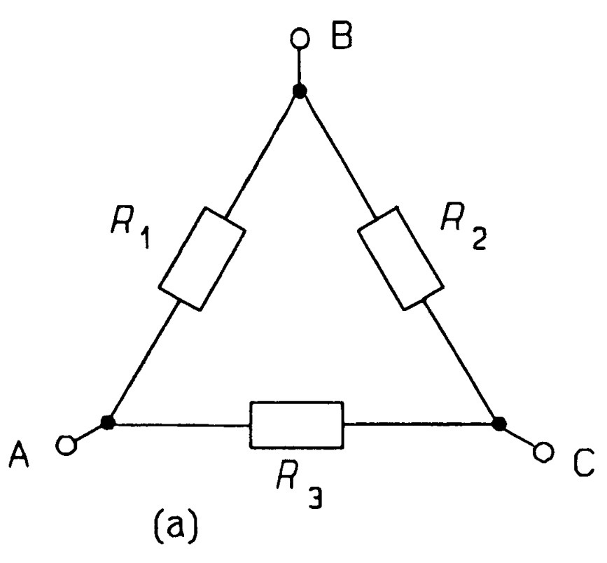
Delta Network - (2 marks)
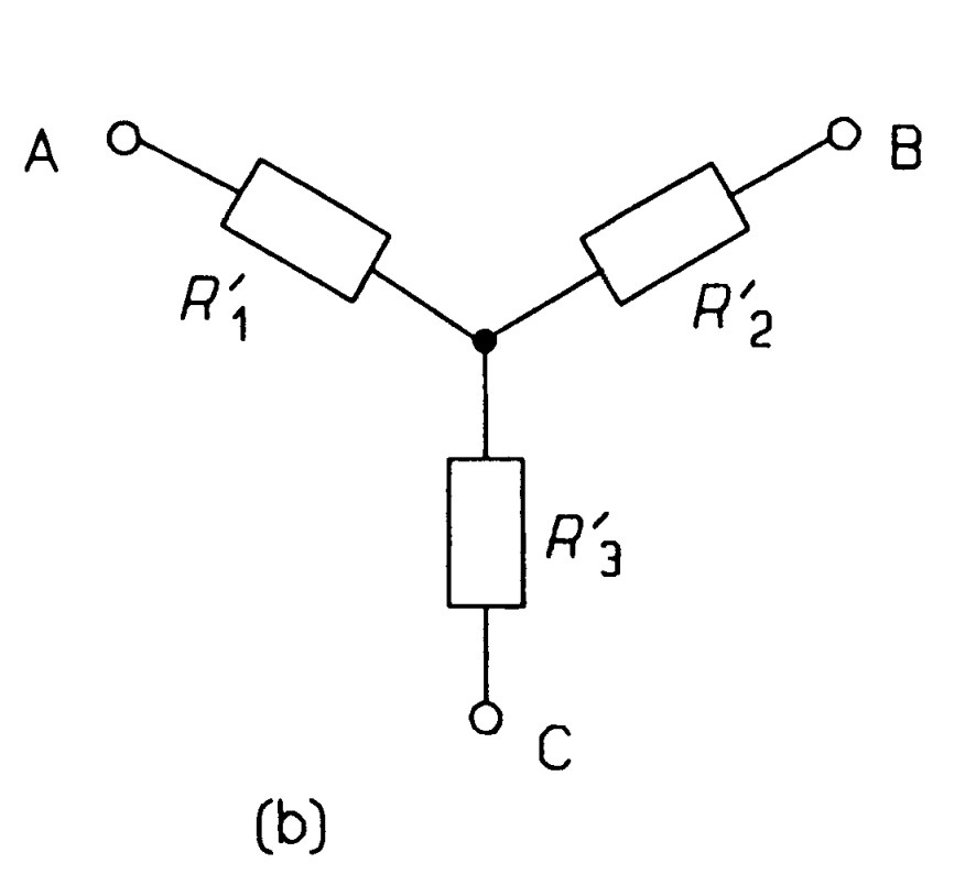
Equivalent resistances for a Star network - (5 marks)
To calculate the resistance of the network of figure between terminals \(1\) and \(4\), we see that it comprises \(R_3\) in parallel with the series resistances, \(R_1\) and \(R_2\). In symbols, \(R_3 || (R_1 + R_2)\), to give (by the product-over-sum rule)
\[\frac{R_3(R_1 + R_2)}{R_1 + R_2 + R_3} =\frac{R_3(R_1 + R_2)}{\sum~R} ~~~~~~~~~~~~~~~~(1)\]where \(\sum~R = R_1 + R_2 + R_3\). Looking into the same terminals in second figure we see the resistance is \(R'_1 + R'_3\) and this must be the same for both networks, that is
\[R'_1 + R'_3= \frac{R_3(R_1 + R_2)}{\sum~R}~~~~~~~~~~~~~~~~(2)\]Then the resistance between terminals 2 and 3 is
\[R'_2 + R'_3= \frac{R_3(R_1 + R_3)}{\sum~R}~~~~~~~~~~~~~~~~(3)\]and looking into terminals 1 and 2 the final equation is obtained
\[R'_1 + R'_2= \frac{R_1(R_2 + R_3)}{\sum~R}~~~~~~~~~~~~~~~~(4)\]Subtracting equations \(2-3\) to find \(R'_1 +R'_2\) :
\[R'_1 - R'_2= \frac{R_1R_3-R_1R_2}{\sum~R}~~~~~~~~~~~~~~~~(5)\]Adding equations 4 and 5 yields
\[2R'_1 = \frac{2R_1R_3}{\sum~R}~~~~~~~~~~~~~~~~(6)\]or
\[R'_1 = \frac{R_1R_3}{\sum~R}~~~~~~~~~~~~~~~~(7)\]Solving for \(R'_2\) and \(R'_3\) similarly leads to
\[R'_2 = \frac{R_1R_2}{\sum~R}~~~~~~~~~~~~~~~~(8)\]and
\[R'_3 = \frac{R_2R_3}{\sum~R}~~~~~~~~~~~~~~~~(9)\]Ans. \(5 \)
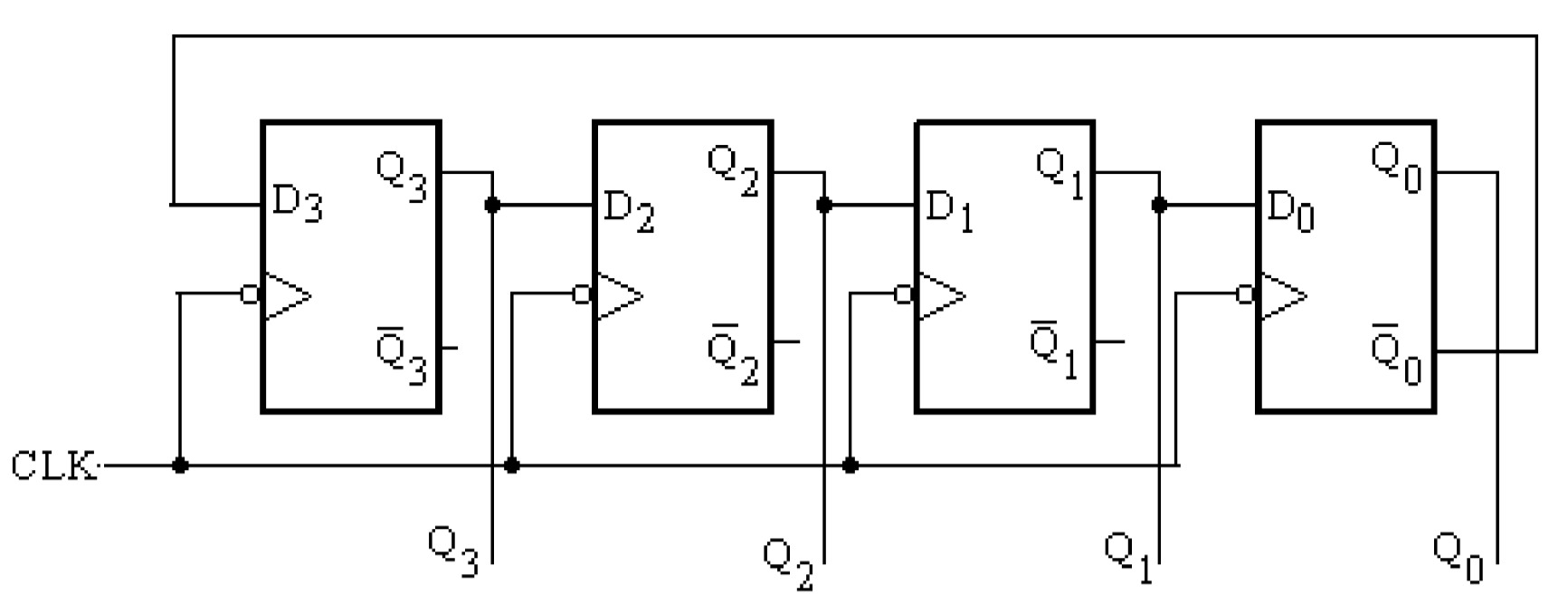
Draw a neat circuit diagram of a \(3\)-bit Johnson counter. - (2 marks)
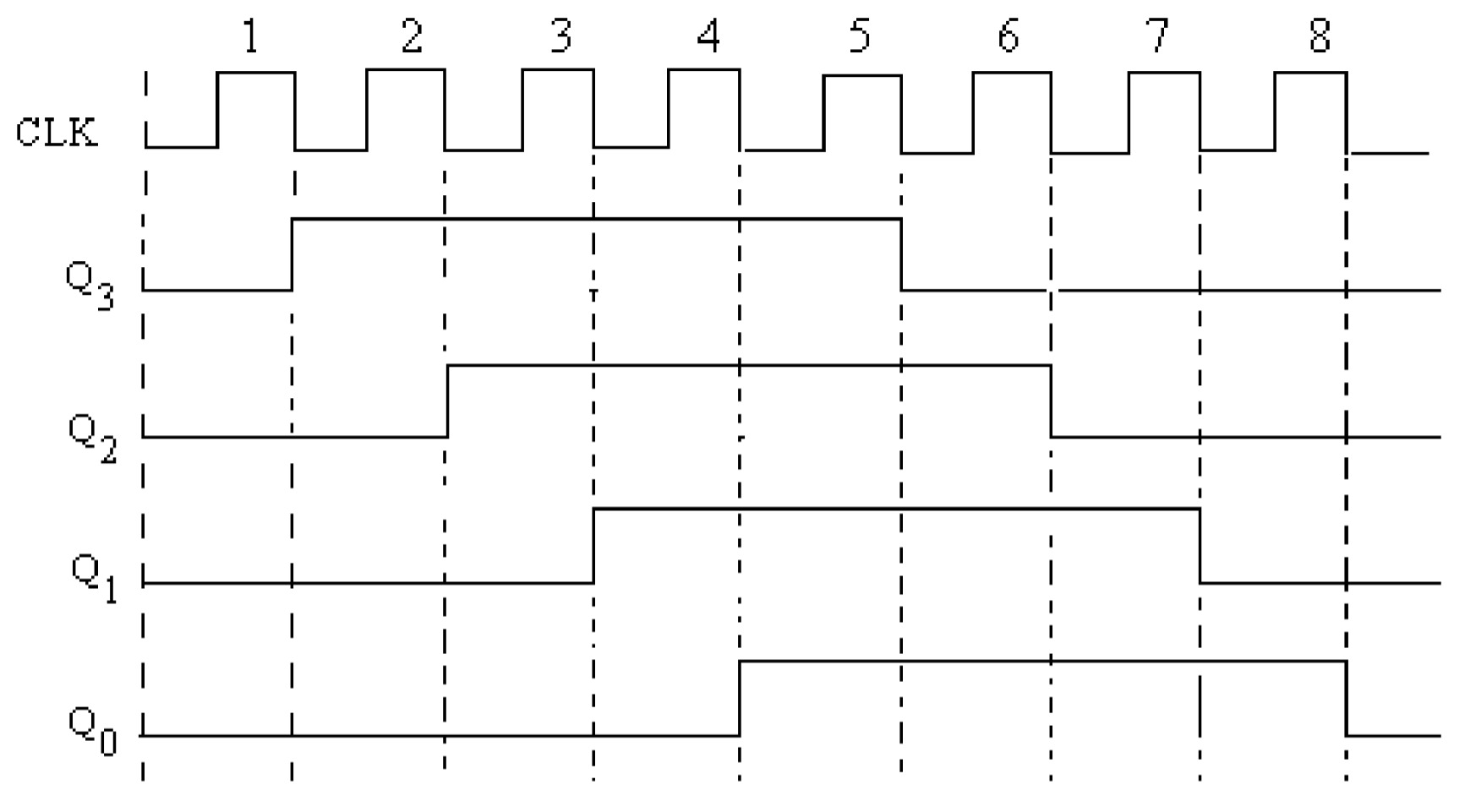
Draw the truth table of a \(3\)-bit Johnson counter - (1 marks)
| Clock | \(Q_{2}\) | \(Q_{1}\) | \(Q_{0}\) |
|---|---|---|---|
| Zero | 0 | 0 | 0 |
| One | 1 | 0 | 0 |
| Two | 1 | 1 | 0 |
| Three | 1 | 1 | 1 |
| Four | 0 | 1 | 1 |
| Five | 0 | 0 | 1 |
Draw the waveform of a \(3\)-bit Johnson Counter - (2 marks)
Ans. \(6 \)
Common Solution of Binary Ladder network - (2 marks)
The expression for the analogue voltage output by a \(n\)-bit binary ladder network is given by:
\[V = \frac{V_{REF}}{2^{n}}\sum \left(b_{n} \times 2^{n-1}\right)\]
for \(5\)-bit case, \(V\) is given as
\[V = \frac{V_{REF}}{2^{5}}\left(b_{5} \times 2^{4}+b_{4} \times 2^{3}+b_{3} \times 2^{2}+b_{2} \times 2^{1}+b_{1} \times 2^{0}\right)\]
\[V_{REF}= 10~ V\]
Hence,
\[V = \frac{10}{32}\left(b_{5} \times 16+b_{4} \times 8+b_{3} \times 4+b_{2} \times 2+b_{1} \times 1\right) \]
(a) \(10111\) - (1\(\frac{1}{2}\) marks)
\[V = \frac{10}{32}\left(1 \times 16+0 \times 8+1 \times 4+1 \times 2+1 \times 1\right) \]
\[V = \frac{10}{32}\left( 16+0 + 4+ 2+ 1\right) \]
\[V = \frac{10}{32}\left( 23\right)= \frac{230}{32}= 7.1875~ V\]
(b) \(01101\) - (1\(\frac{1}{2}\) marks)
\[V = \frac{10}{32}\left(0 \times 16+1 \times 8+1 \times 4+0 \times 2+1 \times 1\right) \]
\[V = \frac{10}{32}\left(0 + 8+ 4+0 +1 \right) \]
\[V = \frac{10}{32}\left(13 \right)= \frac{130}{32}=4.0625 ~V\]
Ans. \(7 \)
(a) Sum of the Products - (2\(\frac{1}{2}\) marks)
\(f(A, B, C) = \sum (0, 1, 3, 5) + \sum_d (2, 7)\)
\[f(A, B, C) = \overline{A}~\overline{B}~\overline{C}+ \overline{A}~\overline{B}C+\overline{A}BC+A\overline{B}C\]
Don't care conditions: \[\overline{A}B\overline{C}, ABC\]
Karnaugh map is given as
| \(_{C}\diagdown ^{AB}\) |
| \(00\) | \(01\) | \(11\) | \(10\) |
| \(0\) |
| \(1\) |
| \(1\) | \(d\) | \(0\) | \(0\) |
| \(1\) | \(1\) | \(d\) | \(1\) |
The minimized sum of products form is:
\[f(A, B, C) = \overline{A} + C\]
(b) Product of the Sums - (2\(\frac{1}{2}\) marks)
\(f(A, B, C) = \prod (4, 6) + \prod_d (2, 7)\)
\[f(A, B, C)=(\overline{A}+B+C)(\overline{A}+\overline{B}+C) \]
Don't care conditions: \[(A+\overline{B}+C)(\overline{A}+\overline{B}+\overline{C})\]
Karnaugh map is given as
| \(_{C}\diagdown ^{AB}\) |
| \(00\) | \(01\) | \(11\) | \(10\) |
| \(0\) |
| \(1\) |
| \(d\) | \(0\) | \(0\) | \(0\) |
| \(1\) | \(1\) | \(0\) | \(d\) |
The minimized product of sums form is also:
\[f(A, B, C) = \overline{A} + C\]
Ans. \(8 \)
\(Y=ABC +AB\overline{C} +A\overline{B}C +A\overline{B}~\overline{C} +\overline{A}BC +\overline{A}B\overline{C} +\overline{A}~\overline{B}~\overline{C} +\overline{A}~\overline{B}C\)
Solution Steps using Boolean Algebra - (4 marks)
\[Y=AB(C +\overline{C}) + A\overline{B}(C +\overline{C}) +\overline{A}B(C +\overline{C}) +\overline{A}~\overline{B}(\overline{C} +C)\] \[Y=AB + A\overline{B} +\overline{A}B +\overline{A}~\overline{B}\] \[Y=A(B + \overline{B}) +\overline{A}(B + \overline{B})\] \[Y=A +\overline{A}\] \[Y=1\]
Karnaugh map is given as
| \(_{C}\diagdown ^{AB}\) |
| \(\overline{A}~\overline{B}\) | \(\overline{A}B\) | \(AB\) | \(A\overline{B}\) |
| \(\overline{C}\) |
| \(C\) |
| \(1\) | \(1\) | \(1\) | \(1\) |
| \(1\) | \(1\) | \(1\) | \(1\) |
Final Answer after solution - (1 marks)
\[Y = 1\]
Ans. \(9 \)
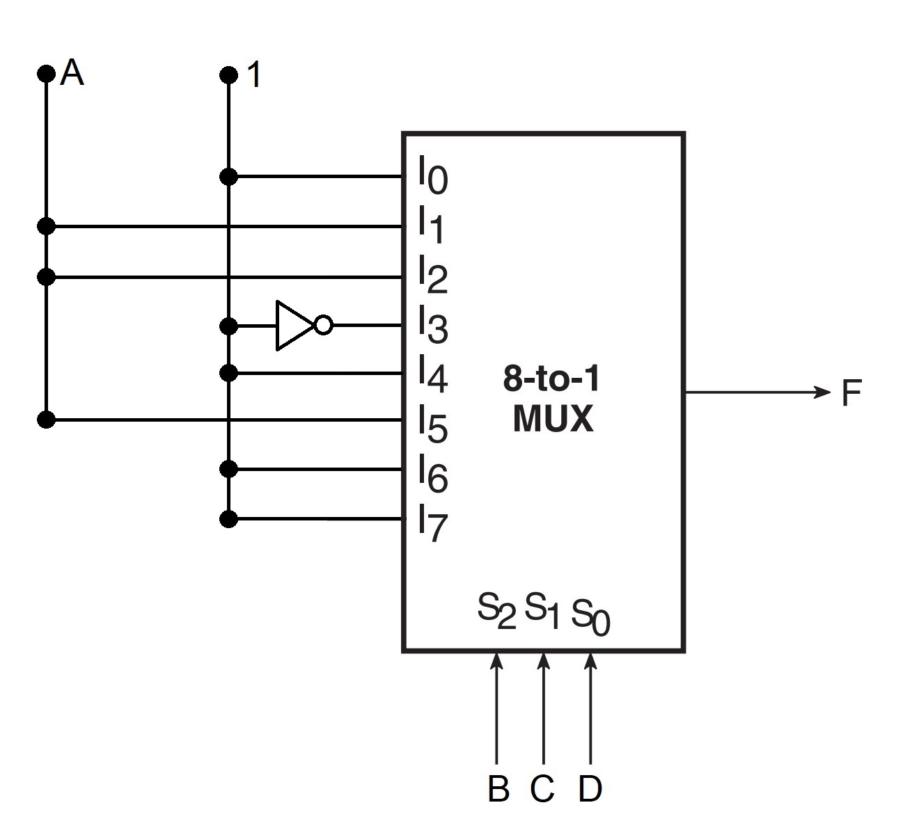
\(F_{1} (A,B,C,D)=\sum (0,4,6,7,8,9,10,12,13,14,15)\)
Truth table
| A | B | C | D | Y |
|---|---|---|---|---|
| 0 | 0 | 0 | 0 | 1 |
| 0 | 0 | 0 | 1 | 0 |
| 0 | 0 | 1 | 0 | 0 |
| 0 | 0 | 1 | 1 | 0 |
| 0 | 1 | 0 | 0 | 1 |
| 0 | 1 | 0 | 1 | 0 |
| 0 | 1 | 1 | 0 | 1 |
| 0 | 1 | 1 | 1 | 1 |
| 1 | 0 | 0 | 0 | 1 |
| 1 | 0 | 0 | 1 | 1 |
| 1 | 0 | 1 | 0 | 1 |
| 1 | 0 | 1 | 1 | 0 |
| 1 | 1 | 0 | 0 | 1 |
| 1 | 1 | 0 | 1 | 1 |
| 1 | 1 | 1 | 0 | 1 |
| 1 | 1 | 1 | 1 | 1 |
Analysis of the truth table concludes the realization of 16:1 Mux table with 8:1 Mux as per the input configurations:
\[I_{0}=1, \] \[I_{1}=A,\] \[I_{2}=A, \] \[I_{3}=0, \] \[I_{4}=1, \] \[I_{5}=A, \] \[I_{6}=1, \] \[I_{7}=1 \]
Circuit realization using \(8:1\) \(MUXs\)
Ans. \(10 \)
Statement of Maximum Power transfer theorem
*Maximum power is transferred to a load resistance connected between two terminals of a network when the load resistance is equal to the resistance of the network measured between the same two terminals, the sources of the network being replaced by their internal resistances. *
Proof of the Maximum Power transfer theorem
The proof is as follows. Any two-terminal network can be reduced to a single voltage source in series with a resistance (Thevenin's theorem), as in the figure.
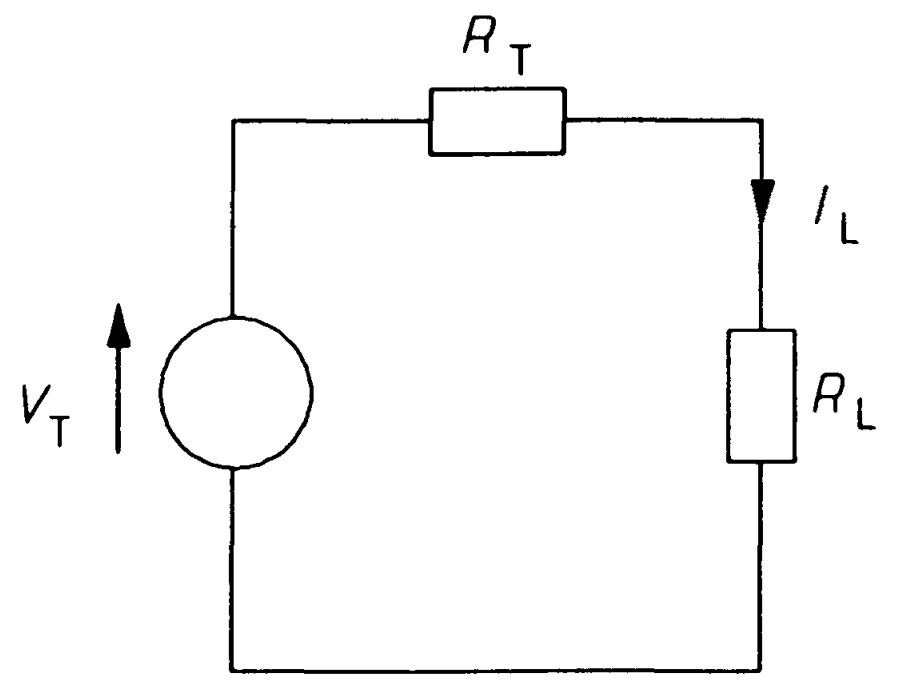
If a resistance, \(R_L\) is attached across AB, the current through it by Ohm's law is
\[I_L=\frac{V_T}{(R_T+R_L)}~~~~~~~~~~~~~~~~~~~~(1)\]
The power developed in the load is
\[P_L=I_L^2R_L=\left[\frac{V_T}{(R_T+R_L)}\right]^2R_L~~~~~~~~~~~~~~~~~~~~(2)\]
Differentiating with respect to \(R_L\) and equating to zero for turning points in \(P_L\)
\[\frac{dP_L}{dR_L}=\left[\frac{V_T^2(R_T+R_L)^2-2V_T^2(R_T+R_L)R_L}{(R_T+R_L)^4}\right]=0~~~~~~~~~~~~~~~~~~~~(3)\]
\[V_T^2(R_T+R_L)^2=2V_T^2(R_T+R_L)R_L~~~~~~~~~~~~~~~~~~~~(4)\]
\[R_T +R_L = 2R_L~~~~~~~~~~~~~~~~~~~~(5) \]
that is
\[R_T = R_L~~~~~~~~~~~~~~~~~~~~(6)\]
It is left as an exercise to check that this condition leads to maximum power in the load by deciding if \(\frac{d^2P_L}{dR_L^2}\) is negative. The maximum power transfer theorem is reduced to:
Maximum power is transferred from a resistive network when the load resistance is equal to the Thevenin resistance of the network.
When \(R_T = R_L\), the current through the load must be \(V_T/2R_L\), so the maximum power developed will be \(\frac{I^2_{max}}{R_L}\), or
\[P_{max}=\left(\frac{V^2_TR_L}{2R^2_L}\right)=\left(\frac{V^2_T}{4R_L}\right) ~~~~~~~~~~~~~~~~~~~~(7)\]