Electric Power Distribution
Electricity is a particularly useful and convenient form of ordered energy. Because it’s delivered to our homes and offices as a utility, we barely think about it, except to pay the bills. The wires that bring it to us never plug up or need cleaning and work continuously except when there’s a power failure, blown fuse, or tripped circuit breaker.
Electricity is dangerous, particularly when it involves high voltages. The principal hazard is that an electric current will pass through your body in the vicinity of your heart and disrupt its normal rhythm. Very little current is needed to cause trouble, but your skin is such a poor conductor that it normally prevents harmful currents from passing through you. Be careful around high voltages, however, because they can propel dangerous currents through your skin and put you at risk. Although your body usually has to be part of a closed circuit for you to receive a shock, don’t count on the absence of an identifiable circuit to protect you from injury—circuits have a tendency to form in surprising ways whenever you touch an electric wire. Be especially careful whenever you’re near voltages of more than 50 V, even in batteries, or when you’re near any voltages if you’re wet or your skin is broken. That said, voltages of 12 V or less are so unlikely to injure you that they are generally considered safe. Nearly all household batteries provide voltages in that safe range and can be handled individually with little risk of shock. Similarly, most power adapters for electronic devices provide 12 V or less and thus rarely cause shocks.
Direct Current Power Distribution
Batteries may be fine for powering flashlights, but they’re not very practical for lighting homes. Early experiments that placed batteries in basements were disappointing because the batteries ran out of energy quickly and needed service and fresh chemicals all too frequently. A more cost-effective source for electricity was coal- or oil-powered electric generators. Like batteries, generators do work on the electric currents flowing through them and can provide the electric power needed to illuminate homes. But although generators produce electricity more cheaply than batteries, early ones were large machines that required fresh air and attention. These generators had to be built centrally, with people to tend them and chimneys to get rid of the smoke.
This was the approach taken by the American inventor Thomas Alva Edison (1847– 1931) in 1882 when he began to electrify New York City following his development of a practical incandescent lightbulb. Each of the Edison Electric Light Company’s generators acted like a mechanical battery, producing direct current (DC) that always left the generator through one wire and returned to it through another. Edison placed his generators in central locations and conducted the current to and from the homes he served through copper wires. However, the farther a building was from the generator, the thicker the copper wires had to be. That’s because wires impede the flow of current and making them thicker allows them to carry current more easily.
Wire thickness is important because The wire’s wasted power is proportional to the square of the current passing through it! This relationship became all too clear to Edison when he tried to expand his power distribution systems. The more current he tried to deliver over a particular wire, the more power it lost as heat. Doubling the current in the wire quadrupled the power it wasted.
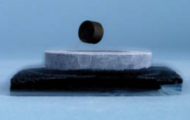
Edison tried to combat this loss by lowering the electrical resistances of the wires. He used copper because only silver is a better conductor of current. He used thick wires to increase the number of moving charges. He also kept the wires short so that they didn’t have much chance to waste power. This length requirement forced Edison to build his generating plants within the cities he served. Even New York City contained many local power plants. Edison also tried to minimize waste by decreasing the currents in the wires while increasing the voltage differences between those wires. Delivered power is equal to the current times the voltage drop, so while less current flowed through each home, the larger voltage drop left the delivered power unchanged. The voltage difference between the two wires carrying current to and from a home is often referred to as the voltage of the electric power. Using that terminology, Edison needed to provide large-voltage or “high-voltage” DC electric power to his customers. High voltage power is dangerous, however, because it can cause fire-starting sparks and nasty shocks. It could be handled safely outside a home, but bringing it inside was another matter. Edison used the highest voltage power that safety allowed. Although scientists have discovered a number of materials that lose their electrical resistance at extremely low temperatures and become perfect electrical conductors, or superconductors, these superconductors are still too impractical for power distribution systems. Their use is limited to local applications such as large electromagnets and specialized electronic devices.
The real problem with distributing electric power via direct current is that there’s no easy way to transfer power from one DC circuit to another. Because the generator and the lightbulbs must be part of the same circuit, safety requires that the entire circuit use low voltages and large currents. DC power distribution therefore wastes much of its power in the wires connecting everything together.
Alternating Current
An alternating current is one that periodically reverses direction-it alternates. Alternating voltages are present at any AC electrical outlet. In the United States, an ordinary AC outlet offers three connections: hot, neutral, and ground. In a properly installed outlet, the absolute voltage of neutral remains near 0 V, while the absolute voltage of hot alternates above and below 0 V. Ground, which is an optional safety connection that we’ll discuss later, also remains near 0 V absolute. In normal AC electric power, the hot voltage varies sinusoidally—it’s proportional to the trigonometric sine function with respect to time. This smoothly alternating voltage propels a smoothly alternating current through the toaster. During each reversal, the current in the heating element gradually slows to a stop before gathering strength in the opposite direction. In the United States, AC voltages reverse every 120th of a second, yielding 60 full cycles of reversal (back and forth) each second (60 Hz). In Europe, the reversals occur every 100th of a second, so AC voltages complete 50 full cycles of reversal each second (50 Hz). The power consumption is defined as an effective voltage for AC electric power. An outlet’s nominal AC voltage—technically, its root mean square (RMS) voltage—is defined to be equal to the DC voltage that would cause the same average power consumption in an ohmic device. Thus, 120-V AC power delivers the same average power to a toaster as 120-V DC power. AC power’s sinusoidally varying voltages peak well above their nominal values, exceeding those values by a factor of the square root of 2 (about 1.414). For example, the voltage of the hot connection in an ordinary 120-V AC power outlet actually swings between +170 V and -170 V. Those higher peak voltages are important for insulation and electrical safety.
Magnetic Induction
The champion of alternating current was Nikola Tesla (1856–1943), a Serbian American inventor who was backed financially by the American inventor and industrialist George Westinghouse (1846–1914). The advantage that Tesla and Westinghouse saw in alternating current was that its power could be transformed—it could be passed via electromagnetic action from one circuit to another by a device called a transformer. A transformer uses two important connections between electricity and magnetism to convey power from one AC circuit to another. The first is familiar: moving electric charge creates magnetic fields. This connection allows electricity to produce magnetism. The second connection, however, is something new: magnetic fields that change with time create electric fields. Discovered in 1831 by Michael Faraday , this relationship allows magnetism to produce electricity
Whether you wave a permanent magnet back and forth, or switch an electromagnet on and off, you are changing a magnetic field with time and thereby producing an electric field. If there are mobile electric charges around to respond to that electric field, they’ll accelerate and you’ll have created or altered an electric current and possibly done work on it as well. This process, whereby a time-changing magnetic field initiates or influences an electric current, is called magnetic induction. A transformer combines these two connections in sequence—electricity produces magnetism produces electricity. However, rather than returning electric power to where it started, the transformer moves that power from the current in one coil of wire through a magnetic field to the current in a second coil of wire.
Alternating Current and a Coil of Wire
What happens when you send an alternating current through a single coil of wire? Because currents are magnetic, the coil becomes an electromagnet. However, since the current passing through it reverses periodically, so does its magnetic field. Also, because a magnetic field that changes with time produces an electric field, the coil’s alternating magnetic field produces an alternating electric field. This induced electric field has a remarkable effect—it pushes on the very alternating current that produces it! Although it’s not obvious how this electric field should affect that current, the result turns out to be simple. As the coil’s current increases, the induced electric field pushes that current backward and thereby opposes its increase. As the coil’s current decreases, the induced electric field pushes that current forward and thereby opposes its decrease. No matter how the coil’s current changes, the induced electric field always opposes that change!
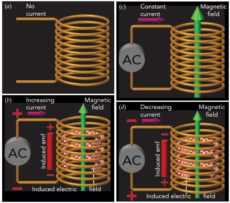
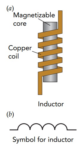
This opposition to change is universal in magnetic induction, where it’s known as Lenz’s law: when a changing magnetic field induces a current in a conductor, the magnetic field from that current opposes the change that induced it. In other words, the effects of magnetic induction oppose the changes that produce them. In the present case, self-directed magnetic induction or “self-inductance” leads our coil to oppose its own changes in current. A wire coil’s natural opposition to current change makes it quite useful in electrical equipment and electronics, where it’s called an inductor.
However, our coil’s induced electric field does more than just push the current around; it can also do positive or negative work on that current and thereby shift that current from one voltage to another. The coil’s overall voltage shift, from one end of the coil to the other, is known as its induced emf (short for electromotive force). Current enters the coil at one voltage and exits at another voltage, courtesy of the coil’s induced emf.
A coil’s ability to shift an alternating current gracefully from one voltage to another makes it possible to plug a properly designed coil into an AC electric outlet without causing disaster. As the outlet’s voltage difference alternates, the coil’s induced emf follows that voltage difference perfectly. Magnetic induction keeps the coil’s current small and, if we neglect the coil’s tiny electrical resistance, none of the AC electric power is wasted as thermal power.
As the coil’s voltage difference and induced emf alternate, the coil’s current keeps trying to flow from higher voltage to lower voltage. The coil’s opposition to current change, however, delays the current’s response so that its alternating current lags a quarter of an AC cycle behind its alternating voltage difference. For example, the current reaches its peak flow toward the top of the coil a quarter of an AC cycle after the voltage at the top of the coil reached its peak positive value. Although the coil’s voltage difference and current both vary sinusoidally with time, the current has a phase shift or phase delay of 90° relative to the voltage difference.
Because of this phase shift, current flows through the coil from higher voltage to lower voltage only half the time. The other half, current flows from lower voltage to higher voltage. When current flows toward lower voltage, the induced emf removes electrostatic potential energy from the current. When current flow toward higher voltage, the induced emf returns electrostatic potential energy to the current. Energy alternately leaves the current and returns.
Magnetic fields contain energy. The amount of energy in a uniform magnetic field is half the square of the field strength times the volume of the field divided by the permeability of free space.
\[energy = \frac{magnetic~ field^{2} · volume}{2 · permeability ~of ~free ~space}\]
in symbols:
\[U = \frac{B^{2} · V}{2 · \mu_{0}}\]
and in everyday language:
Strong permanent magnets store so much magnetic energy that they can be dangerous if you break them. The pieces will flip around violently, and you may get pinched.
In effect, our coil is playing with the alternating current’s energy, storing it briefly in the magnetic field and then returning it to the current. The coil stores energy while the magnitude of the current increases—the field strengthens and the current loses voltage. The coil returns energy while the magnitude of the current decreases—the field weakens and the current gains voltage. Because the coil’s self-induced emf is responsible for bouncing this energy back to the current, it’s frequently called a back emf.
Two Coils Together: A Transformer
A single coil experiences only self-inductance. Any energy removed from the coil’s current by its induced emf must eventually be returned to that same current; it has nowhere else to go. But when two coils share the same electromagnetic environment, they experience mutual inductance and can exchange energy via magnetic induction. Energy removed from one coil’s current by its induced emf can be given to the other coil’s current by its induced emf.
That possibility is the basis for a transformer, a device that transfers electric power from one circuit to another. In its simplest form, a transformer consists of two coils, primary and secondary, wrapped around a magnetizable core that enhances magnetic induction and allows them to share the same electromagnetic environment. When alternating current flows through the primary coil, it produces an induced electric field that affects both coils and both coils develop induced emfs. The induced emf in the primary coil removes energy from its alternating current while the induced emf in the secondary coil gives that energy to its alternating current.
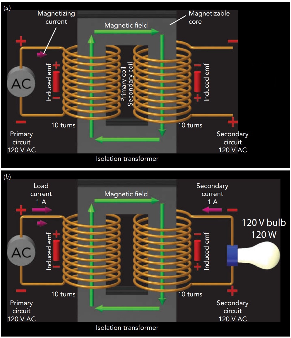
A generator provides its primary coil with 120-V AC electric power, while its secondary coil is an open circuit. With the generator subjecting the primary coil to an alternating voltage difference, the primary coil behaves like an inductor. It carries an alternating current and develops an induced emf that exactly matches the voltage difference imposed by the generator. Although the coil’s current naturally tries to flow from higher voltage to lower voltage, the coil’s self-inductance opposes current changes and delays the current’s response. As a result, the coil’s alternating current lags a quarter of an AC cycle or 90 degrees in phase behind the coil’s alternating voltage difference.
Because of its 90-degree phase lag, this alternating current conveys no average power from the generator to the primary coil. Nonetheless, it plays an important role in the transformer: it alternately magnetizes and demagnetizes the transformer’s core and thereby produces the induced emfs in both coils. For that reason, it is known as the magnetizing current.
The transformer’s secondary coil is identical to its primary coil, except for being upside down on the right side of the magnetizable core. The secondary coil’s induced emf is therefore identical to that of the primary coil, except for being upside down. Though it’s an open circuit and can’t carry a significant current, the secondary coil has a voltage difference across it due to the induced emf and it can thus act as a source of 120-V AC electric power!
In Fig., the transformer’s secondary is connected to a lightbulb. Because the lightbulb’s filament obeys Ohm’s law, its current remains proportional to the voltage difference across it, even if that voltage difference alternates. With the secondary coil imposing an alternating voltage difference on the filament, that filament carries an alternating current that is synchronized with the voltage difference. That current always flows toward lower voltage in the filament, dropping off energy, and toward higher voltage in the secondary coil, picking up energy. Provided with 120-V AC power by the secondary coil, this particular lightbulb filament carries an AC current of 1 A. The current that is now flowing through the secondary coil has its own magnetic effect on the transformer. Fortunately, that effect is surprisingly simple: it causes an additional current to flow through the primary coil. Known as the load current, this additional current shares the same conducting path as the magnetizing current, like two fleets of cars sharing the same two-lane road. Unlike the magnetizing current, however, the load current is synchronized with the voltage difference across the primary coil and its two effects are different. It produces a magnetic field that exactly cancels the magnetic field of the secondary current and it conveys electric power from the generator to the primary coil.
When a current travels in a circle, the magnetic field inside the circle is proportional to the current. A wire coil guides its current in a circle multiple times, effectively multiplying that current by the number of turns in the coil. The magnetic field inside a coil of wire is thus proportional to the current in the wire times the number of turns in the coil. Since the transformer’s primary and secondary coils are identical, they have the same number of turns. If the currents in those two coils are equal in amount but opposite in direction, their magnetic fields will cancel. The transformer naturally adjusts its load current to achieve that magnetic cancellation. Since the secondary coil has a 1-A alternating current flowing through it toward higher voltage, the primary coil acquires a 1-A alternating load current flowing through it toward lower voltage. Their magnetic fields cancel perfectly, leaving the magnetizing current solely responsible for the transformer’s magnetic field and its induced emfs. Because the coils are identical, their induced emfs are both 120-V AC. The negative work that the primary coil’s induced emf does on its 1-A current is therefore equal in amount to the positive work that the secondary coil’s induced emf does on its 1-A current.
Overall, the transformer is transferring an AC power of 120 W from the current in its primary circuit to the current in its secondary circuit. To maintain their magnetic cancellation, the load current automatically mirrors any changes in the secondary current. For example, if we add a second lightbulb to the secondary circuit and thereby double the current in the secondary coil, the load current will also double. Because of this mirroring effect, the transformer always consumes as much power from its primary circuit as is consumed by its secondary circuit.
When a source of AC electric power is connected to a transformer’s primary coil, the transformer’s primary and secondary coils both develop induced emfs. If the secondary coil is identical to the primary coil, their induced emfs are equal and the secondary coil becomes a source of AC power at the same voltage as that received by the primary coil. For example, if you plug the transformer’s primary coil into a 120-V AC outlet, its secondary coil will provide 120-V AC electric power to the secondary circuit. A transformer with identical coils is known as an isolation transformer and it provides an important measure of electrical safety. Since its primary and secondary circuits are electrically isolated, charge can’t move between those circuits and cause trouble.
Changing Voltages
Most transformers, however, have unequal coils and therefore different induced emfs in those coils. They provide AC power at voltages that are different from those they receive. The primary coil’s induced emf naturally matches the voltage difference applied to it, but the secondary coil’s emf can vary. It depends on the number of secondary turns—the number of times the secondary coil’s wire encircles the magnetizable core. The more loops the secondary current makes around the core, the more positive or negative work the transformer’s induced electric field does on that current and the larger the secondary coil’s induced emf.
Since the secondary coil’s induced emf is proportional to its number of turns, it acts as a source of AC power with a voltage equal to the voltage applied to the primary coil times the ratio of secondary turns to primary turns.
secondary voltage = primary volatge \[·\frac{secondary turns}{primary turns}\]
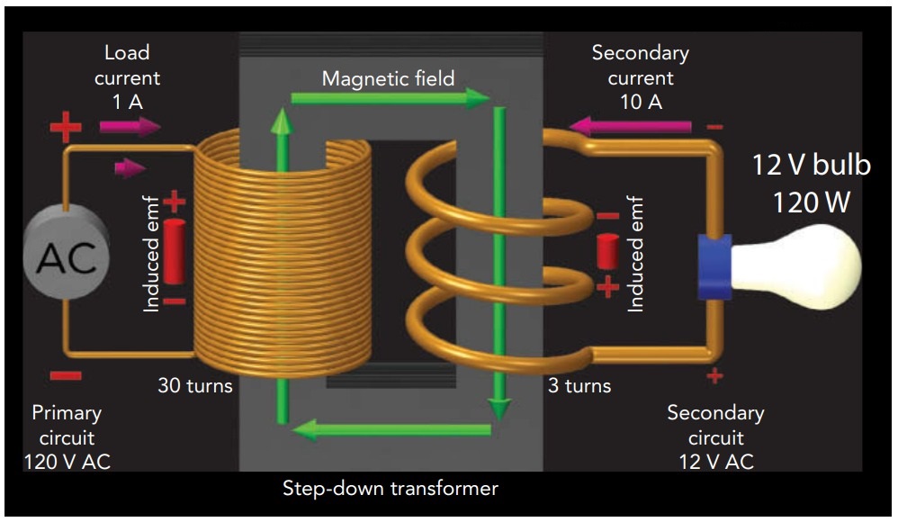
An isolation transformer is simply the special case in which the turn numbers are equal and their ratio is 1. When a transformer has fewer secondary turns than primary turns, it provides a secondary voltage that is less than the primary voltage and is called a step-down transformer. Step-down transformers are common in electronic devices and power adapters, where they step household AC voltages down to much smaller AC voltages. For example, if a transformer’s ratio of secondary turns to primary turns is 0.1 and you supply 120-V AC power to its primary coil, its secondary coil will act as a source of 12-V AC power. Not surprisingly, there are also step-up transformers that have more secondary turns than primary turns and that provide secondary voltages that are greater than their primary voltages. The transformer that powers a neon sign typically has 100 times as many turns in its secondary coil as in its primary coil. When its primary coil is supplied by 120-V AC power, its secondary coil provides the 12,000-V AC power needed to illuminate the neon tube. Even when a transformer has unequal coils, the magnetic fields produced by the load current in its primary coil and the secondary current in its secondary coil must still cancel. Since each coil’s magnetic field is proportional to its current times its number of turns, the coil with fewer turns must compensate by carrying a larger current. As a result, a transformer’s secondary current is equal to its primary load current times the ratio of primary turns to secondary turns, ordered
\[secondary current = primary load current · \frac{primary turns}{secondary turns}\]
where those currents flow in opposite directions; the primary load current flows toward lower voltage in the primary coil while the secondary current flows toward higher voltage in the secondary coil. The secondary voltage is proportional to that ratio, while the secondary current is inversely proportional to that ratio. As you can see, changing a transformer’s ratio of secondary turns to primary turns affects both the voltage and the current in the secondary circuit.
The product of those two quantities, secondary voltage and secondary current, no longer depends on the turn ratio and it’s the power provided to the secondary circuit. It’s also equal to the primary voltage times the primary load current, which is the power received from the primary circuit. The transformer is providing the same power to its secondary circuit as it’s receiving from its primary circuit!
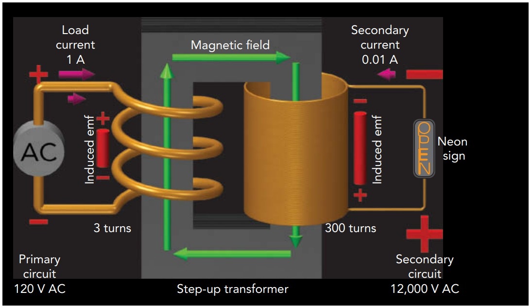
An isolation transformer transfers AC power without any change in voltage or current; the secondary circuit has the same voltage and the same current as in the primary circuit. With a step-down transformer, the secondary circuit has a smaller voltage and a larger current than in the primary circuit. With a step-up transformer, the secondary circuit has a larger voltage and a smaller current than in the primary circuit.
Real Transformers: Not Quite Perfect
In reality, the wires used in those devices have electrical resistances and waste power in proportion to the squares of the currents they carry. To minimize this wasted power, real inductors and transformers are designed to minimize their resistances. To the extent it is practical, they employ thick wires made of highly conducting metals and those wires are kept as short as possible. Unfortunately, inductors and transformers built from wires alone can’t develop strong magnetic fields and large induced emfs unless they carry large magnetizing currents or have long, many-turn coils. To avoid those current or coil problems, many inductors and virtually all transformers wrap their coils around magnetizable cores. Those cores respond magnetically to the alternating currents around them, enhancing their magnetic fields and increasing the induced emfs. Aided by those magnetizable materials—typically iron or iron alloys—cored inductors and transformers work well even with short, few-turn coils. A core provides another crucial benefit to a transformer; it guides the transformer’s magnetic flux lines so that nearly all of them pass through both coils, even when those coils are somewhat separated in space. Sharing their flux lines in that manner gives the coils a common electromagnetic environment and permits them to exchange electric power easily.
Making two separate coils share their flux lines isn’t easy. Since a coil has no net magnetic pole, each flux line that emerges from it must ultimately return to it. Without a core, however, most flux lines leaving a coil return to it almost directly and remain nearby throughout their trip. Those unadventurous flux lines are unlikely to pass through a second, separate coil. Not surprisingly, a coreless transformer works well only when its two coils are wound so closely together that they can’t help but share the same flux lines. Winding both coils around a ring-shaped magnetic core makes it easy for the flux lines to pass through both coils because those flux lines are drawn into the core’s soft magnetic material and follow it as if in a pipe. Although the flux lines leaving a coil must still return to it eventually, most of them complete that trip by way of the core—a journey that then takes them through the other coil. With nearly all the flux lines channeled by the core through both coils, power can flow easily from one coil to the other. A core thus provides a transformer with great flexibility; its coils can be practically anywhere as long as they encircle that core. However, cores aren’t quite perfect pipes for flux; they leak slightly. Therefore, the most efficient transformers have coils that are wound nearby or on top of one another.
Although magnetizable cores make small efficient transformers practical, they also introduce a few problems. First, the cores must magnetize and demagnetize easily to keep up with the magnetizing current in the primary coil. If they lag behind, they’ll waste power as thermal power. Sadly, perfect magnetic softness is unobtainable and all cores waste at least a little power through delays in their magnetizations. Second, because these cores are subject to the same electric fields that push currents around in the coils, they shouldn’t conduct electricity. If they do, they’ll develop useless internal currents known as eddy currents and thereby waste power heating themselves up. Since most soft magnetic materials are electrical conductors, transformer cores are frequently divided up into insulated particles or sheets so that little or no current can flow through them. Despite best efforts at minimizing resistive heating in their coils, and magnetization and eddy current losses in their cores, all transformers still waste some power. Even the best transformers are only about 99% energy efficient.
Alternating Current Power Distribution
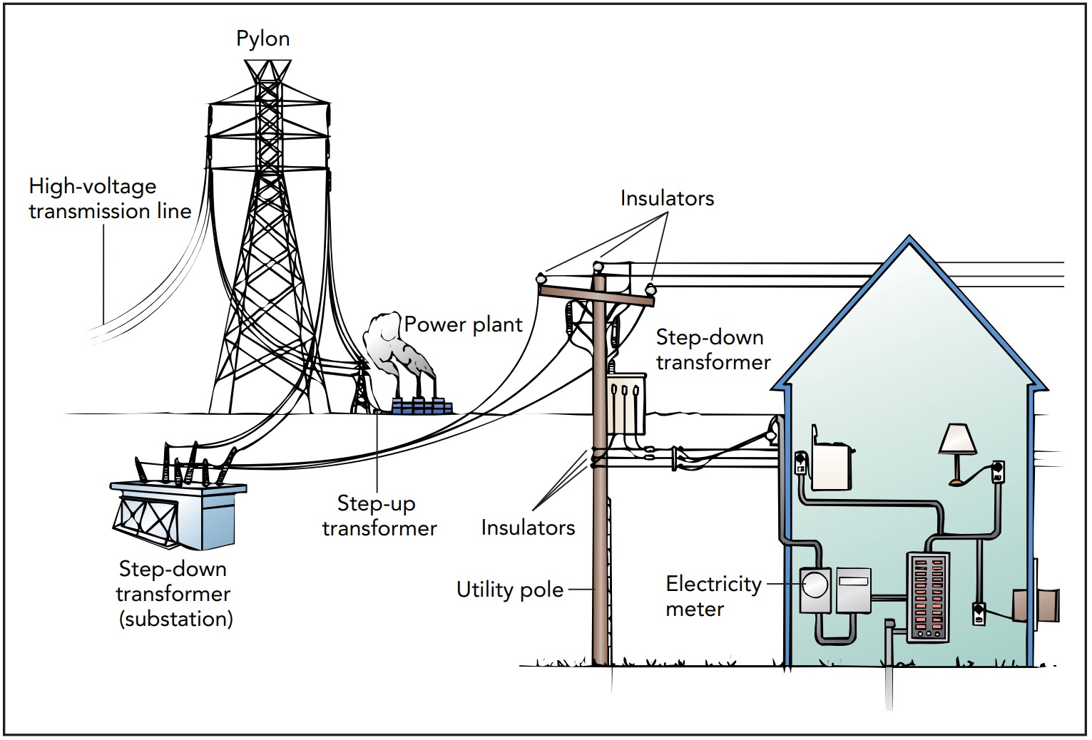
To minimize resistive heating in the power lines connecting a power plant with a distant city, electric power should travel through those lines as small currents at very high voltages. To be practical, though, as well as to avoid shock and fire hazard, electric power should be delivered to homes as large currents at modest voltages. Although there is no simple way to meet both requirements simultaneously with direct current, transformers make it easy to satisfy them both with alternating current. We can use a step-up transformer to produce the very-high-voltage AC electric power suitable for cross-country transmission and a step-down transformer to produce the low-voltage AC electric power that’s appropriate for delivery to communities.
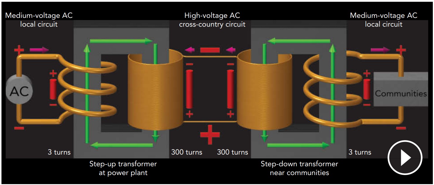
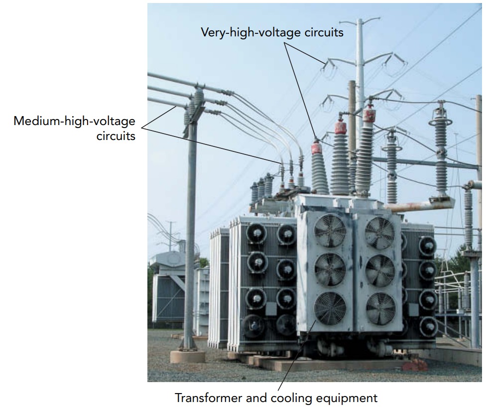
At the power plant, the generator pushes a huge alternating current through the primary circuit of a step-up transformer at a supply voltage of about 5000 V AC. The current flowing through the secondary circuit is only about 1/100 the current in the primary circuit, but the voltage supplied by the secondary coil is much higher, typically about 500,000 V AC. This transformer’s secondary circuit is extremely long, extending all the way to the city where the power is to be used. Since the current in this circuit is modest, the power wasted in heating the wires is within tolerable limits.
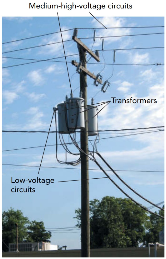
Once it arrives in the city, this very-high-voltage AC electric power passes through the primary coil of a step-down transformer. The voltage provided by the secondary coil of this transformer is only about 1/100 the voltage supplied to its primary coil, but the current flowing through the secondary circuit is about 100 times the current in its primary circuit. Now the voltage is reasonable for use in a city. Before entering homes, this voltage is reduced still further by other transformers. The final step-down transformers can frequently be seen as oil-drum-size metal cans hanging from utility poles or as green metal boxes on the ground. Current enters the buildings at between 110 and 240 V AC, depending on the local standards. Although 240-V AC electricity wastes less power in home wiring, it’s more dangerous than 110-V AC power. The United States has adopted a 120-V AC standard, and Europe has a 230-V AC standard.
AC Electric Generators and Motors
The electric power and mechanical power are physically equivalent, and mechanical power can substitute for electric power. If we replace the transformer’s primary circuit with a mechanical system, we obtain a generator. A generator is a device that extracts mechanical power from machinery and delivers electric power to a circuit. Figure shows a simple generator. Both devices have a (secondary) coil wrapped around a magnetizable core. However, in place of the transformer’s primary coil, the generator has a spinning magnet, or rotor. As the generator’s magnetic rotor spins, it produces a sinusoidally alternating magnetic field in the core. This alternating magnetic field, in turn, produces an alternating electric field and an alternating induced emf in the coil. That emf propels an alternating current through the circuit that delivers electric power to the lightbulb.
The current in the generator’s coil has consequences for its rotor. The rotor turns slightly ahead of the generator’s alternating magnetic field, so that the rotor’s magnetic field cancels the current’s magnetic field. Because the rotor is a little ahead the generator’s alternating magnetic field, it experiences a backward torque and has mechanical power extracted from it. To keep the rotor spinning, the machinery must continue to supply mechanical power to the generator. Overall, the generator is converting mechanical power into electric power.
If we replace the transformer’s secondary circuit with a mechanical system, we obtain a motor. A motor is a device that extracts electric power from a circuit and delivers mechanical power to machinery. Figure shows a simple motor, one that again resembles the transformer in Fig. Like the transformer, the motor has a (primary) coil wrapped around a magnetizable core. In place of the transformer’s secondary coil, however, the motor has a spinning magnetic rotor. As an alternating current flows through the motor’s circuit and coil, it produces a sinusoidally alternating magnetic field in the coil. That alternating magnetic field interacts with the magnetic rotor and delivers mechanical power to it. The rotor’s motion has consequences for the current in the motor’s coil. If the rotor is spinning freely and remains perfectly synchronized with the core’s alternating magnetic field, it has no effect on the core’s magnetic field or the current in the coil. If the rotor is doing mechanical work, however, it needs a forward torque to keep it spinning and it obtains that torque by turning slightly behind the motor’s alternating magnetic field. The rotor’s magnetic field then causes a load current to flow through the motor’s coil. That load current delivers power to the motor and its magnetic field cancels the rotor’s magnetic field. Overall, the motor is converting electric power into mechanical power.
Notice that electrical generators and electrical motor are almost mirror images of one another. That’s because generators and motors are wonderfully similar devices. In fact, a single device can often act as either a generator or a motor. If you supply electric power to its circuit, its rotor will spin and provide mechanical power. If you supply mechanical power to its rotor, current will flow through its circuit and provide electric power.