Electric and magnetic fields are so intimately related that each can create the other even in empty space. In fact, the two fields can form electromagnetic waves, in which they recreate one another endlessly and head off across space at an enormous speed. These electromagnetic waves are all around us and are the basis for much of our communications technology, for radiative heat transfer, and for our ability to see the universe in which we live.
Radio
A fluctuating electric current can represent sound information, and that’s what it does each time you speak into a microphone or listen to music through earphones.
In 1865, *Scottish physicist James Clerk Maxwell (1831–1879) discovered one additional source of magnetic fields: changing electric fields. That effect is subtle and scientists overlooked it for most of the nineteenth century. It wasn’t until Maxwell was trying to formulate a complete electromagnetic theory that he uncovered this additional connection between electricity and magnetism. This final relationship completed the set shown in Table. Taken together, these relationships allowed Maxwell to understand one of the most remarkable phenomena in nature—electromagnetic waves!
| Sources of Electric Fields | Sources of Magnetic Fields |
|---|---|
| Electric charges and subatomic particles | Magnetic poles and subatomic particles |
| Moving magnetic pole | Moving electric charge |
| Changing magnetic fields | Changing electric fields |
Since electric fields can create magnetic fields and magnetic fields contain energy, it’s clear that electric fields must contain energy, too. The amount of energy in a uniform electric field is the square of the field strength times the volume of the field divided by 8p times the Coulomb constant.
\[energy = \frac{electric ~field^{2} · volume} {8\pi · Coulomb ~constant}\]
in symbols:
\[U = \frac{E^{2} · V}{8\pi · k}\]
and in everyday language:
When you charge a large capacitor, it stores a great deal of energy in the electric field between its plates.
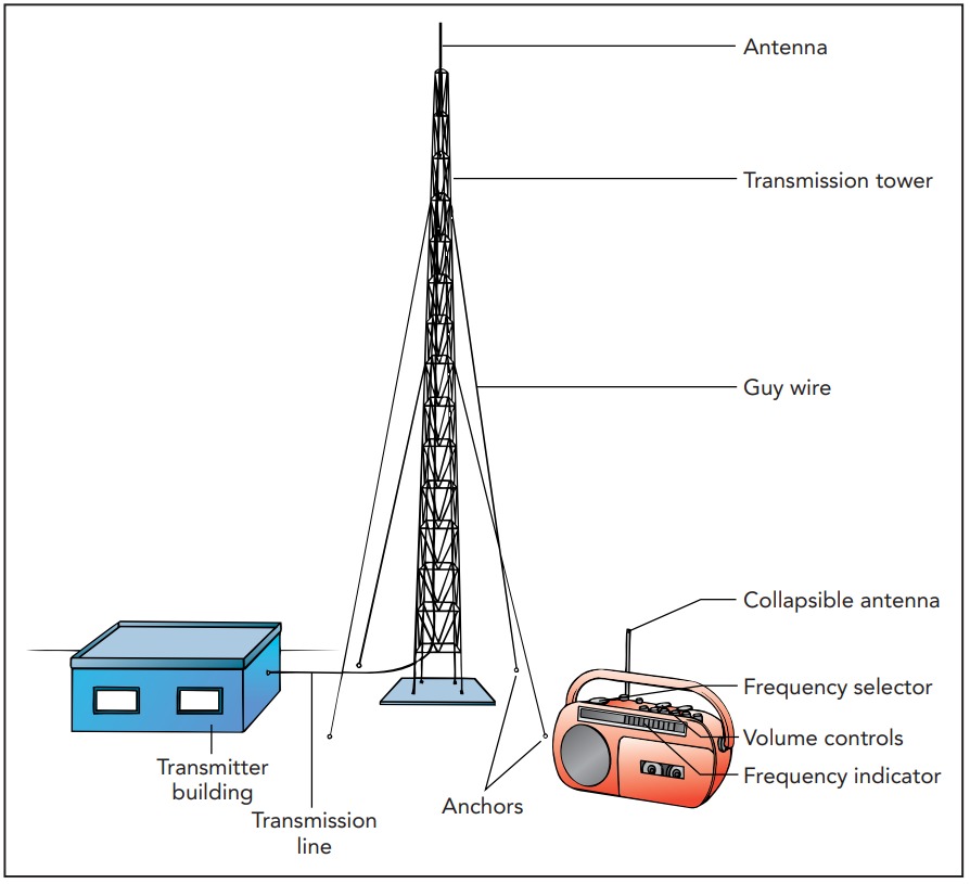
Antennas and Tank Circuits
A radio transmitter communicates with a receiver via radio waves. These waves are produced by electric charge as it moves up and down the transmitter’s antenna and are detected when they push electric charge up and down the receiver’s antenna.
Accelerating charge produces a mixture of changing electric and magnetic fields that can reproduce one another endlessly and travel long distances through empty space. These interwoven electric and magnetic fields are known generally as electromagnetic waves. In the case of radio, the electromagnetic waves have low frequencies and long wavelengths, and are known as radio waves.
Figure shows a radio transmitter and a radio receiver, side by side. Because of their proximity, electric charge on the transmitter’s antenna is sure to affect charge on the receiver’s antenna. To communicate with the nearby receiver, the transmitter sends charge up and down its antenna. This charge’s electric field surrounds the transmitting antenna and extends all the way to the receiving antenna, where it pushes charge down and up. Unfortunately, the resulting charge motion in the receiving antenna is weak and the receiver may have difficulty distinguishing it from random thermal motion or from motion caused by other electric fields in the environment. Therefore the transmitter adopts a clever strategy—it moves charge up and down its antenna rhythmically at a particular frequency. Since the resulting motion on the receiving antenna is rhythmic at that same frequency, it’s much easier for the receiver to distinguish from unrelated motion.
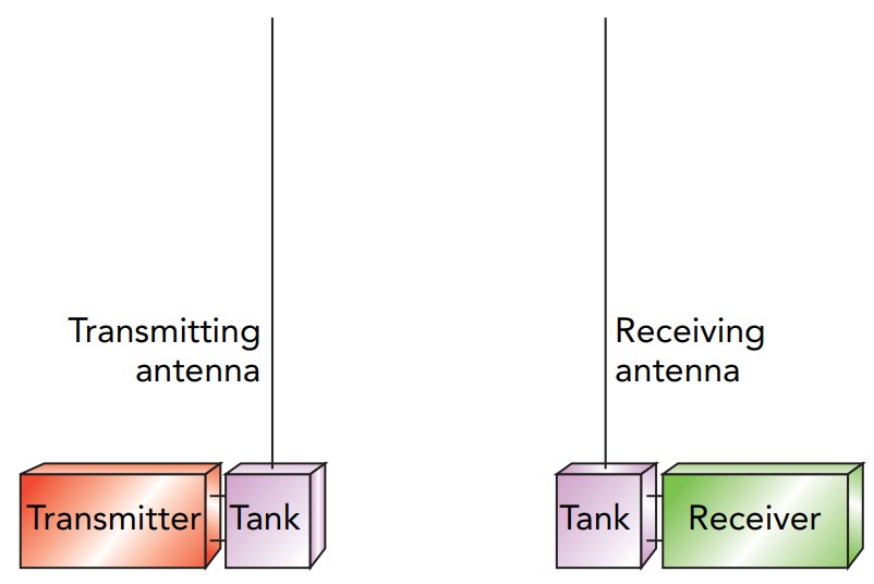
Using this rhythmic motion has another advantage: it allows the transmitter and receiver to use tank circuits, resonant electronic devices consisting only of capacitors and inductors. Charge can “slosh” back and forth through a tank circuit at a particular frequency, much as water can slosh back and forth in a water storage tank at a particular frequency. Just as you can get the water sloshing strongly by giving it gentle pushes that are synchronized with its rhythmic motion, so the transmitter can get charge sloshing strongly through its tank circuit by giving that charge gentle pushes that are synchronized with its rhythmic motion. Both are examples of resonant energy transfer. By helping the transmitter move larger amounts of charge up and down the antenna, the tank circuit dramatically strengthens the transmission. A second tank circuit attached to the receiving antenna helps the receiver detect this transmission. Gentle, rhythmic pushes by fields from the transmitting antenna cause more and more charge to move through the receiving antenna and its attached tank circuit. While the motion of charge on this antenna alone may be difficult to detect, the much larger charge sloshing in the tank circuit is unmistakable.
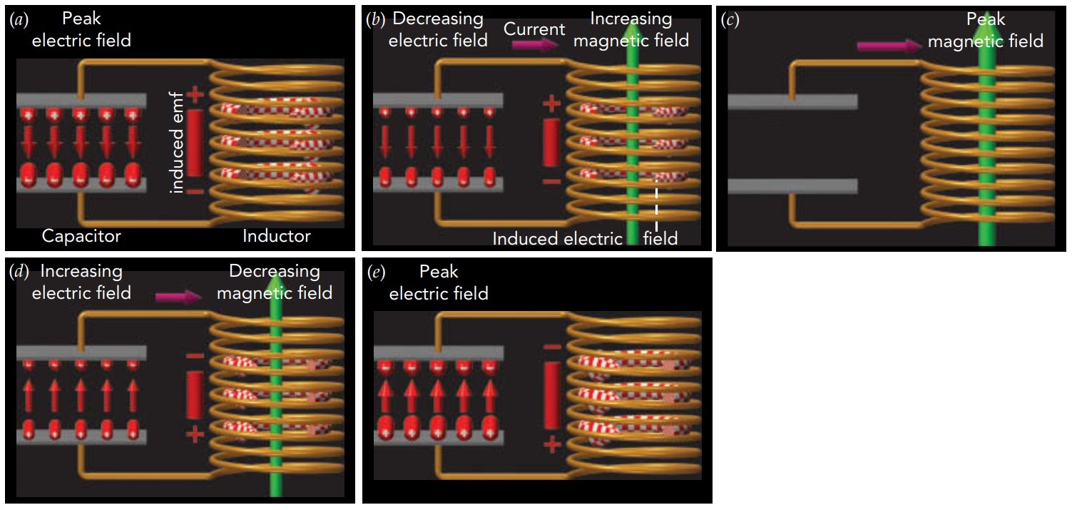
Let’s imagine that the tank circuit starts out with separated charge on the plates of its capacitor. Since the inductor conducts electricity, current begins to flow from the positively charged plate, through the inductor, to the negatively charged plate. The current through the inductor must rise slowly and, as it does, it creates a magnetic field in the inductor. Soon the capacitor’s separated charge is gone and all the tank circuit’s energy is stored in the inductor’s magnetic field. However, the current keeps flowing, driven forward by the inductor’s opposition to current changes. The inductor uses the energy in its magnetic field to keep the current flowing, and separated charge reappears in the capacitor. Eventually, the inductor’s magnetic field decreases to zero and everything is back to its original state—almost. While all the tank circuit’s energy has returned to the capacitor, the separated charge in that capacitor is now upside down. This whole process now repeats in reverse. The current flows backward through the inductor, magnetizing it upside down, and the tank circuit soon returns to its original state. This cycle repeats over and over again, with charge sloshing from one side of the capacitor to the other and back again. A tank circuit is an electronic harmonic oscillator.
The tank circuit’s period depends only on its capacitor and its inductor. The larger the capacitor’s capacitance, the more separated charge it can hold with a given amount of energy and the longer it takes that charge to move through the circuit as current. The larger the inductor’s inductance, its opposition to current changes, the longer that current takes to start and stop. A tank circuit with a large capacitor and a large inductor may have a period of a thousandth of a second or more, while one with a small capacitor and a small inductor may have a period of a billionth of a second or less. Inductance is defined as the voltage drop across the inductor divided by the rate at which current through the inductor changes with time. This division gives inductance the units of voltage divided by current per time. The SI unit of inductance is the volt-second per ampere, also called the henry (abbreviated H). While large electromagnets have inductances of hundreds of henries, a 1-µH (0.000001-H) inductor is more common in radio.
Its resonant behavior makes the tank circuit useful in radio. That’s because small, rhythmic pushes on the current in a tank circuit can lead to enormous charge oscillations in that circuit. In radio, these rhythmic pushes begin when the transmitter sends an alternating current through a coil of wire. Fields from this coil push current back and forth through the nearby transmitting tank circuit, causing enormous amounts of charge to slosh back and forth in it and travel up and down the transmitting antenna. That charge’s electric field then pushes rhythmically on charge in the receiving antenna, causing substantial amounts of charge to travel down and up it and slosh back and forth in the receiving tank circuit. The receiver can easily detect this sloshing charge. Energy flows from the transmitter to the receiver via resonant energy transfer: from the transmitter, to the transmitting tank circuit and antenna, to the receiving antenna and tank circuit, and finally to the receiver. This sequence of transfers can work efficiently only if all the parts have resonances at the same frequency. Tuning a radio receiver to a particular station is largely a matter of adjusting its capacitor and inductor so that its tank circuit has the right resonant frequency.
Radio Waves
When the two antennas are close together, charge in the transmitting antenna exerts electrostatic force directly on charge in the receiving antenna. However, when the antennas are far apart, the interactions between them are more complicated. Charge in the transmitting antenna must then emit a radio wave to push on charge in the receiving antenna. Like a water wave, a radio wave is a disturbance that carries energy from one place to another. But unlike a water wave, which must travel in a fluid, a radio wave can travel through otherwise empty space, from one side of the universe to the other.
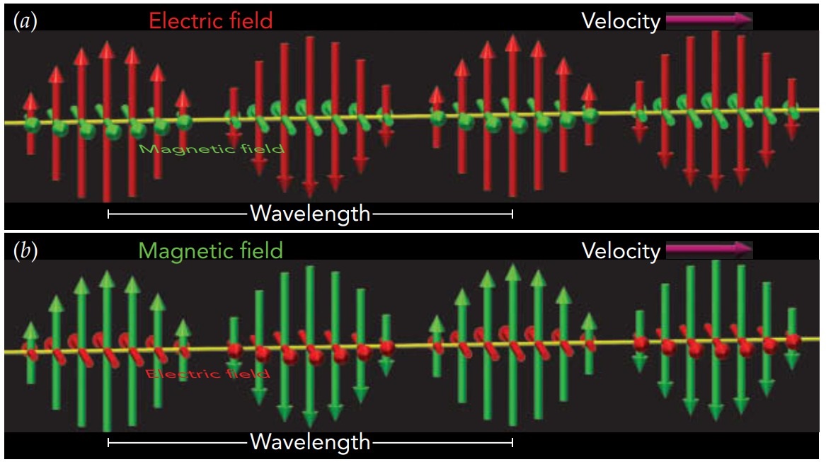
Like all electromagnetic waves, a radio wave consists only of a changing electric field and a changing magnetic field. These fields re-create one another over and over again as the wave travels through empty space at the speed of light—exactly 299,792,458 m/s (approximately 186,282 miles per second).
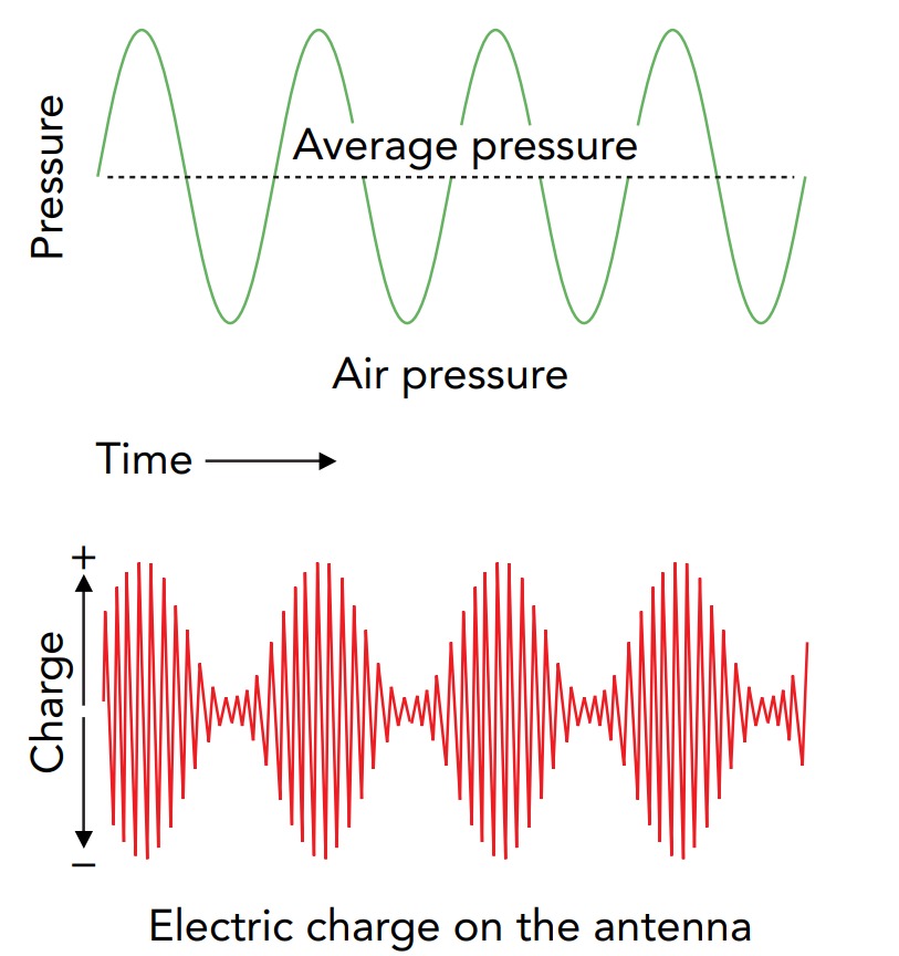
The radio wave is created when electric charge in the antenna accelerates. Whereas stationary charge or a steady current produces constant electric or magnetic fields, accelerating charge produces fields that change with time. As charge flows up and down the antenna, its electric field points in alternating directions vertically, and its magnetic field points in alternating directions horizontally. These changing fields then re-create one another again and again, and sail off through space as an electromagnetic wave. At each point along its path, the wave’s electric field direction, magnetic field direction, and direction of travel are mutually perpendicular.
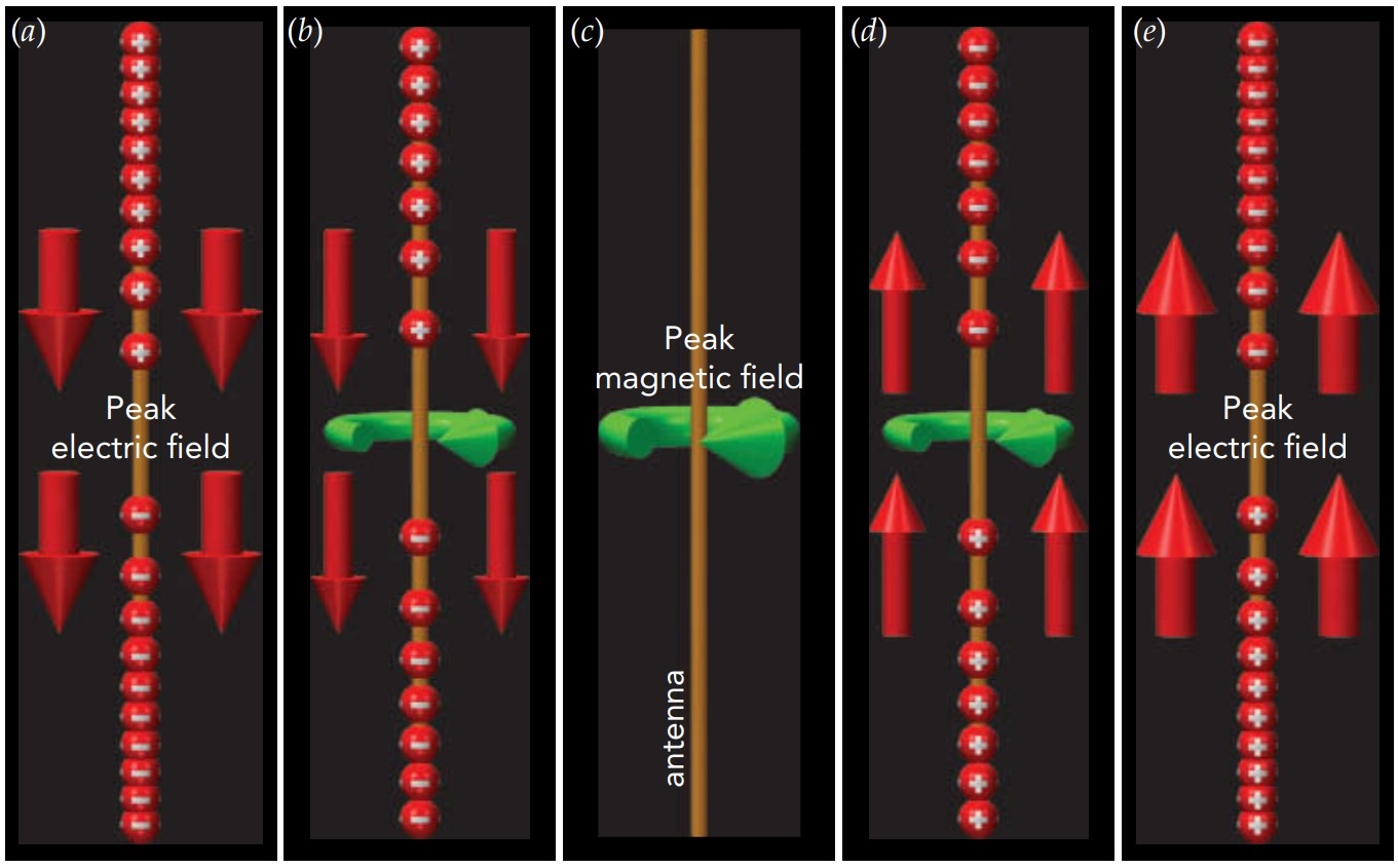
The wave emitted by a vertical transmitting antenna has a vertical polarization, that is, its electric field points alternately up and down. We identify those “ups” as crests, and the distance between adjacent crests is its wavelength. For radio waves, that wavelength is usually 1 m (3.3 ft) or more. The wave’s magnetic field is perpendicular to its electric field and points in alternating directions horizontally. Had the transmitting antenna been tipped on its side, the wave’s electric field would have pointed in alternating directions horizontally and the wave would have had a horizontal polarization. The wave’s magnetic field would then point alternately up and down. Whatever the polarization, the electric and magnetic fields move forward together as a traveling wave, so the pattern of fields moves smoothly through space at the speed of light.
If you stood in one place and could watch this wave pass, you’d notice its electric field fluctuating up and down at the same frequency as the charge that created it. When the wave passes a distant receiving antenna, it pushes charge up and down that antenna at this frequency. If the receiving tank circuit is resonant at this frequency, the amount of charge sloshing in it should become large enough for the receiver to detect. A radio station can optimize its transmission by using a resonant transmitting antenna. A straight antenna is another electronic harmonic oscillator, with a period that depends only on its length. When that length is half the wavelength of the radio wave it’s transmitting, charge sloshes up and down the antenna in a natural resonance at the frequency of the radio wave.
The antenna is actually a tank circuit—its tips act as the plates of a capacitor and its middle acts as the inductor. Despite its linear shape, the antenna has the same resonant behavior as the coiled tank circuit shown in Fig. When the transmitting tank circuit and antenna are resonant at the same frequency, there’s a resonant energy transfer from one to the other. These resonant effects help to produce a powerful radio wave. Many radio stations use such antennas. It’s possible, however, to omit the bottom half of the dipole antenna by placing the top half above an electrically conducting surface. The conducting surface is a mirror and its reflection of the top half acts like the missing bottom half of the dipole antenna. Known as a quarter-wave monopole antenna, this shorter antenna is often more convenient, particularly when the antenna projects upward from a metal surface or the ground.
The transmitting antenna sends the strongest portion of its radio wave out perpendicular to its length. That’s not unexpected because the motion of charge on the antenna is most obvious when viewed from a line perpendicular to its length. Thus, a vertical antenna sends most of its wave out horizontally, where people are likely to receive it. No wave emerges from the end of an antenna. Both electric and magnetic fields contain energy, so as the electromagnetic wave travels through space, it carries energy away from the transmitter. When a radio station advertises that it “transmits 50,000 W of music,” it’s claiming that its antenna emits 50,000 J of energy per second or 50,000 W of power in its electromagnetic wave. The receiving antenna must absorb enough of this power to detect the wave. However, the farther the wave gets from the transmitting antenna, the more spread out and weaker it becomes. Trees and mountains also absorb or reflect some of the wave and hinder reception.
For the best reception, a listener should be located where the radio wave is strong and where there’s an unobstructed path from the transmitting antenna to the receiving antenna. To be resonant, the receiving antenna should be a half-wave dipole or a quarter-wave monopole, and it should be oriented along the radio wave’s polarization: vertical for a vertically polarized radio wave or horizontal for a horizontally polarized radio wave. Aligning the receiving antenna with the wave’s polarization makes certain that the wave’s electric field pushes charge along the antenna, not across it.
To ensure good reception regardless of receiving antenna orientation, many radio stations transmit a complicated circularly polarized wave that combines both vertical and horizontal polarizations. To form this wave, they need several antennas. For wavelengths under a few meters, these antennas can all be attached inexpensively to a single mast. That’s why commercial FM and TV broadcasts, which use short-wavelength radio waves, are usually transmitted with circular polarization. However, commercial AM broadcasts, which use long-wavelength radio waves, are transmitted only with vertical polarization.
Because commercial FM radio waves usually include both polarizations, FM receiving antennas can be vertical or horizontal. Portable FM receivers often use vertical telescoping antennas, while home receivers frequently use horizontal wire antennas. All these antennas are approximately half-wave dipole antennas or quarter-wave monopole antennas.
A quarter-wave monopole antenna for commercial AM radio would have to be about 100 m (330 ft) long, so straight AM antennas (such as those on cars) are much shorter than optimal. That’s why many AM antennas are designed to respond to the radio wave’s horizontal magnetic field rather than to its vertical electric field. These magnetic antennas are horizontal coils of wire that experience induced currents when exposed to fluctuating magnetic fields.
Representing Sound: AM and FM Radio
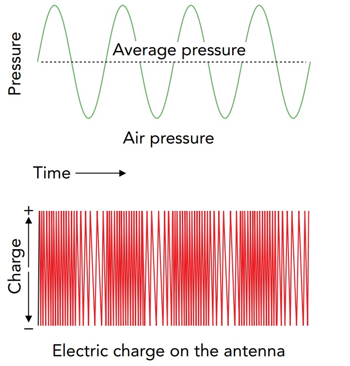
A radio transmitter does more than simply emit a radio wave. It uses that radio wave to represent sound. Because sound waves are fluctuations in air density and radio waves are fluctuations in electric and magnetic fields, a radio wave can’t literally “carry” a sound wave. However, a radio wave can carry sound information and instruct the receiver how to reproduce the sound.
To convey sound information, the radio station alters its radio wave to represent compressions and rarefactions of the air. The receiver then recreates those compressions and rarefactions. There are two common techniques by which a radio wave can represent those density fluctuations. One is called amplitude modulation and involves changing the overall strength of the radio wave. The other is called frequency modulation and involves small changes in the frequency of the radio wave.
In the amplitude modulation (AM) technique, air density is represented by the strength of the transmitted wave. To represent a compression of the air, the transmitter is turned up so that more charge moves up and down the transmitting antenna. To represent a rarefaction, the transmitter is turned down so that less charge moves up and down the antenna. The frequency at which charge moves up and down the antenna remains steady, so only the amplitude of the radio wave changes. The receiver measures the strength of the radio wave and uses this measurement to re-create the sound. When it detects a strong radio wave, it pushes its speaker toward the listener and compresses the air. When it detects a weak radio wave, it pulls its speaker away from the listener and rarefies the air.
In the amplitude modulation (AM) technique, air density is represented by the strength of the transmitted wave. To represent a compression of the air, the transmitter is turned up so that more charge moves up and down the transmitting antenna. To represent a rarefaction, the transmitter is turned down so that less charge moves up and down the antenna. The frequency at which charge moves up and down the antenna remains steady, so only the amplitude of the radio wave changes. The receiver measures the strength of the radio wave and uses this measurement to re-create the sound. When it detects a strong radio wave, it pushes its speaker toward the listener and compresses the air. When it detects a weak radio wave, it pulls its speaker away from the listener and rarefies the air.
In the frequency modulation (FM) technique, air density is represented by the frequency of the transmitted wave. To represent a compression of the air, the transmitter’s frequency is increased slightly so that charge moves up and down the transmitting antenna a little more often than normal. To represent a rarefaction, the transmitter’s frequency is decreased slightly so that the charge moves up and down a little less often than normal. These changes in frequency are extremely small—so small that charge continues to slosh strongly in all the resonant components and reception is unaffected. The receiver measures the radio wave’s frequency and uses this measurement to re-create the sound. When it detects an increased frequency, it compresses the air, and when it detects a decreased frequency, it rarefies the air.
Although the AM and FM techniques for representing sound can be used with a radio wave at any frequency, the most common commercial bands in the United States are the AM band between 550 kHz and 1600 kHz (550,000 Hz and 1,600,000 Hz) and the FM band between 88 MHz and 108 MHz (88,000,000 Hz and 108,000,000 Hz). Elsewhere in the spectrum of radio frequencies are many other commercial, military, and public transmissions, including TV, shortwave, amateur radio, telephone, data, police, and aircraft bands. These other transmissions use AM, FM, and a few other techniques to represent sound and information with radio waves.
Bandwidth and Cable
A pure, single-frequency radio wave doesn’t carry any information. To represent sound, video, or any other form of information, the radio wave must vary with time. Think of smoke signals—a steady stream of smoke carries no information, but carefully timed puffs of smoke can send a message. Once a radio wave is varying with time to carry information, it no longer has a single pure frequency. Regardless of which aspects of the radio wave are varying, that wave now includes a range of frequencies. The more information the radio wave carries each second, the broader that range of frequencies becomes.
When it’s representing sound, a radio wave has a range of radio frequencies that stretches from somewhat below the official frequency of the radio wave, the carrier frequency, to somewhat above that frequency. The wider the audio frequency range of the sound, the more sound information must be sent each second and the broader the range of radio frequencies needed to represent that sound. The range of frequencies needed to transmit such a stream of information is known as the transmission’s bandwidth.
By international agreement, an AM radio station may use 10 kHz of bandwidth, 5 kHz above and below its carrier frequency. To stay within that bandwidth, the sound being represented can’t contain frequencies above 5 kHz. Although this restricted frequency range is bad for music, it allows competing stations to function with carrier frequencies only 10 kHz apart, so 106 different stations can operate between 550 kHz and 1600 kHz. An FM radio station may use 200 kHz of bandwidth, 100 kHz on each side of its carrier frequency. This luxurious allocation permits FM radio to represent a very broad range of audio frequencies, in stereo, which is why an FM radio station can do a much better job of sending music to your radio than an AM station can. In recent years, FM stations have begun using their 200-kHz bandwidths to carry digital information representing several programs of “high-definition” sound.
Because high-frequency radio waves travel in straight lines between antennas, it’s hard to receive a commercial FM station from more than about 100 km (60 mi) away. Even when the transmitting antenna sits on top of a tall tower, Earth’s curvature and surface terrain severely limit the range of FM reception.
Low-frequency radio waves, such as those used by commercial AM stations, are reflected by charged particles in Earth’s outer atmosphere, so portions of the radio wave that would otherwise be lost to space bounce back toward the ground. This returning power allows you to receive AM stations over a considerable distance, even when you have no direct line of sight to the transmitter’s antenna. At sundown, these atmospheric layers become so effective at reflecting AM radio that you can hear a transmission from thousands of kilometers away as clearly as if it were a hometown station.
The spectrum of electromagnetic waves is a limited resource, and if it could only be used once, it would quickly run out of bandwidth. Fortunately, distance and enclosures make it possible to reuse the spectrum many times. Cell phones that are far from one another can share the same carrier frequencies and bandwidth because their radio waves weaken with distance and essentially don’t overlap. However, even nearby radio transmissions can use the same carrier frequencies by enclosing their electromagnetic waves inside cables.
Cable radio, television, and data networks are similar to broadcast networks except that they send electromagnetic waves through cables rather than through empty space. A typical radio or television cable consists of an insulated metal wire inside a tube of metal foil or woven metal mesh. This wire-inside-a-tube arrangement is called coaxial cable because its two metal components share the same centerline or axis. In contrast, a typical computer-data cable consists of a number of insulated metal wires that are twisted into several pairs.
Electromagnetic waves can propagate easily through a coaxial or twisted-pair cable, following its twists and turns from the transmitter that produces the waves to the receiver that uses them. The fact that wires are assisting these waves in their travels makes them more complicated than waves in empty space. However, they still involve electric and magnetic fields and still propagate forward at nearly the speed of light.
Because the electromagnetic waves inside a cable don’t interact with those outside it, the transmitter and receiver can use whatever parts of the spectrum they choose, without concerns about sharing. A typical coaxial cable can handle frequencies up to about 1000 MHz and typical twisted-pair cable can reach 350 MHz, so either one can carry a great deal of information each second.
However, coaxial cables must now compete with optical fiber cables that guide light from one place to another. Like radio waves, light is an electromagnetic wave and can be amplitude or frequency modulated to represent information. However, light’s frequency is extremely high; the frequencies of visible light range from 4.5 \times 10^{14} to 7.5 \times 10^{14} Hz. If we were to allocate FM radio channels 200 kHz apart throughout the visible spectrum, there would be about 1.5 billion channels available!
Microwave Ovens
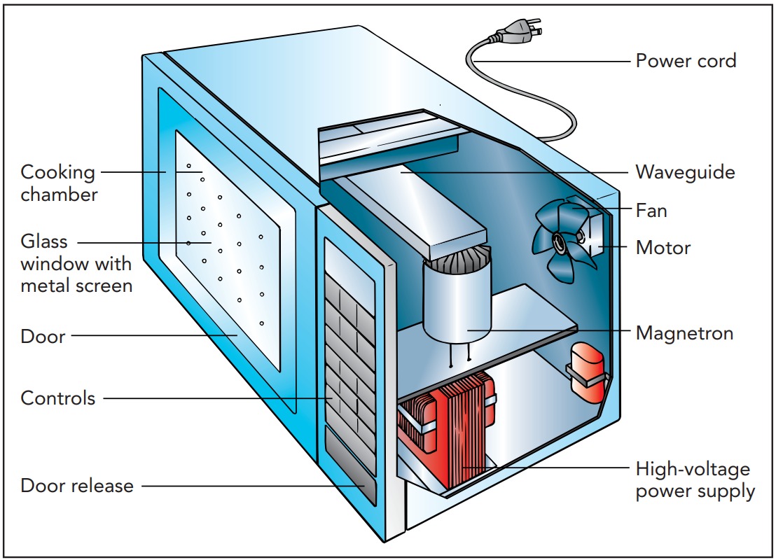
In addition to carrying sounds from one place to another, electromagnetic waves can carry power. One interesting example of such power transfer is a microwave oven. It uses relatively high-frequency electromagnetic waves to transfer power directly to the water molecules in food so that the food cooks from the inside out.
Microwaves and Food
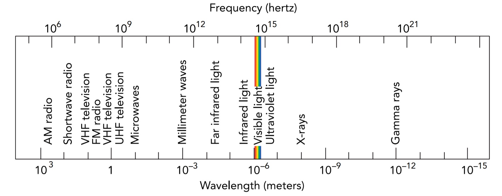
A basic electromagnetic wave in empty space has both a wavelength and a frequency, and their product is the speed of light. That relationship can be written as a word equation:
speed of light = wavelength · frequency
in symbols:
c = \lambda · \nue
and in everyday language:
The higher the frequency of an electromagnetic wave, the shorter its wavelength becomes.
Radio broadcasts use the low-frequency, long-wavelength portion of the electromagnetic spectrum. Commercial AM radio broadcasts at frequencies of 550 to 1600 kHz (wavelengths of 545 to 187 m) and commercial FM radio broadcasts at frequencies of 88 to 108 MHz (wavelengths of 3.4 to 2.8 m). As long as their wavelengths are 1 m (3.3 ft) or longer, electromagnetic waves are called radio waves. Electromagnetic waves that have wavelengths of 1 mm or longer, but less than 1 m, are called microwaves*. Microwave ovens usually cook food with 0.122-m electromagnetic waves.
Microwave oven was devised by American Scientist and Microwave engineer, Percy Lebaron Spencer (1894–1970). In 1945, while visiting a magnetron testing laboratory, he leaned over an operating magnetron and the candy bar in his shirt pocket melted. Immediately recognizing what had happened, he soon had popcorn popping about the lab and even cooked an egg until it exploded. Cooking has never been the same since.
Water molecules are electrically polarized—that is, they have positively charged ends and negatively charged ends. This polarization comes about because of quantum physics and the tendency of oxygen atoms to pull electrons away from hydrogen atoms. The water molecule is bent, with its two hydrogen atoms sticking up from its oxygen atom. When the oxygen atom pulls the electrons partly away from the hydrogen atoms, its side of the molecule becomes negatively charged, while the hydrogen atoms’ side becomes positively charged. Water is thus a polar molecule.
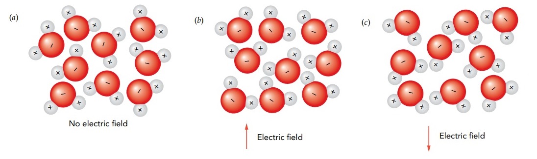
In ice, these polar water molecules are arranged in an orderly fashion with fixed positions and orientations. However, in liquid water, the molecules are more randomly oriented. Their arrangements are constrained only by their tendency to bind together, positive end to negative end, to form a dense network of coupled molecules. This binding between the positively charged hydrogen atom on one water molecule and the negatively charged oxygen atom on another molecule is known as a hydrogen bond. If you place liquid water in a strong electric field, its water molecules will tend to rotate into alignment with the field. That’s because a misaligned molecule has extra electrostatic potential energy and accelerates in the direction that reduces its potential energy as quickly as possible. In this case, the water molecule will experience a torque and will undergo an angular acceleration that makes it rotate into alignment. As it rotates, the molecule will bump into other molecules and convert some of its electrostatic potential energy into thermal energy. If the electric field reverses its direction many times, the water molecules will turn back and forth and become hotter and hotter.
A microwave’s fluctuating electric field is well suited to heating water. A microwave oven uses 2.45-GHz (2.45-gigahertz or 2,450,000,000-Hz) microwaves to twist the food’s water molecules back and forth billions of times per second. As the water molecules turn, they bump into one another and heat up. The water absorbs the microwaves and converts their energy into thermal energy. This particular microwave frequency was chosen not because of any resonant effect but because it was not in use for communications and because it cooks food uniformly. If the frequency were higher, the microwaves would be absorbed too strongly by food and wouldn’t penetrate deeply into large items. If the frequency were lower, the microwaves would pass through food too easily and wouldn’t cook it efficiently. This twisting effect explains why only foods or objects containing water or other polar molecules cook well in a microwave oven. Microwave-safe ceramic plates, glass cups, and plastic containers are water-free and usually remain cool. Even ice has trouble absorbing microwave power because its crystal structure constrains the water molecules so they can’t turn easily.
Although ice melts slowly in a microwave oven, the liquid water it produces heats quickly. This peculiar heating behavior explains why it’s so easy to burn yourself on frozen food heated in a microwave oven. The portions of the food that defrost first absorb most of the microwave power and overheat, while the rest of the food remains frozen solid. You never know whether your next bite will break your teeth or sear the roof of your mouth. To address this problem, many microwave ovens have defrost cycles in which microwave heating is interrupted periodically to let heat flow naturally through the food to melt the ice. Once the frozen parts have melted, all the food can absorb microwaves.