Cryocoolers
Cryocoolers are specialized refrigeration systems that operate at very low temperatures. They are used in a variety of applications, including medical equipment, aerospace, and research laboratories. Cryocoolers work by removing heat from a system and transferring it to a heat sink. They are commonly used to cool superconducting magnets, which require temperatures below 10 K to operate.
The cryocooler is most often used for smaller systems, typically table-top size, with input powers less than about 20 kW. Some can have input powers as low as 2-3 Watts. Large systems, such as those used for cooling the superconducting magnets in particle accelerators are more often called cryogenic refrigerators. Their input powers can be as high as 1 MW. In most cases cryocoolers use a cryogenic fluid as the working substance and employ moving parts to cycle the fluid around a thermodynamic cycle. The fluid is typically compressed at room temperature, precooled in a heat exchanger, then expanded at some low temperature. The returning low-pressure fluid passes through the heat exchanger to precool the high-pressure fluid before entering the compressor intake. The cycle is then repeated.
Cryocoolers can be classified into two categories: mechanical and non-mechanical. Mechanical cryocoolers are the most common type of cryocooler. They work by using mechanical compression to transfer heat from a low-temperature reservoir to a high-temperature heat sink. There are several types of mechanical cryocoolers, including: Stirling cryocoolers, Gifford-McMahon cryocoolers, Pulse-tube cryocoolers and Joule-Thomson cryocoolers.
Stirling cryocoolers use a piston and cylinder to compress and expand a gas. The gas is then used to transfer heat from a low-temperature reservoir to a high-temperature heat sink. Gifford-McMahon cryocoolers use a mechanical compressor to compress and expand a gas. The gas is then used to transfer heat from a low-temperature reservoir to a high-temperature heat sink. Pulse-tube cryocoolers use a high-frequency oscillator to create pressure waves in a gas. The pressure waves are then used to transfer heat from a low-temperature reservoir to a high-temperature heat sink. Joule-Thomson cryocoolers use a throttling valve to expand a gas. The gas is then used to transfer heat from a low-temperature reservoir to a high-temperature heat sink.
Non-mechanical cryocoolers use a different method to transfer heat from a low-temperature reservoir to a high-temperature heat sink. They are typically more expensive than mechanical cryocoolers, but they are also more reliable and require less maintenance. There are several types of non-mechanical cryocoolers, including, Dilution refrigerators and Adiabatic demagnetization refrigerators.
Dilution refrigerators use a mixture of helium-3 and helium-4 to transfer heat from a low-temperature reservoir to a high-temperature heat sink. Adiabatic demagnetization refrigerators use the magnetocaloric effect to transfer heat from a low-temperature reservoir to a high-temperature heat sink.
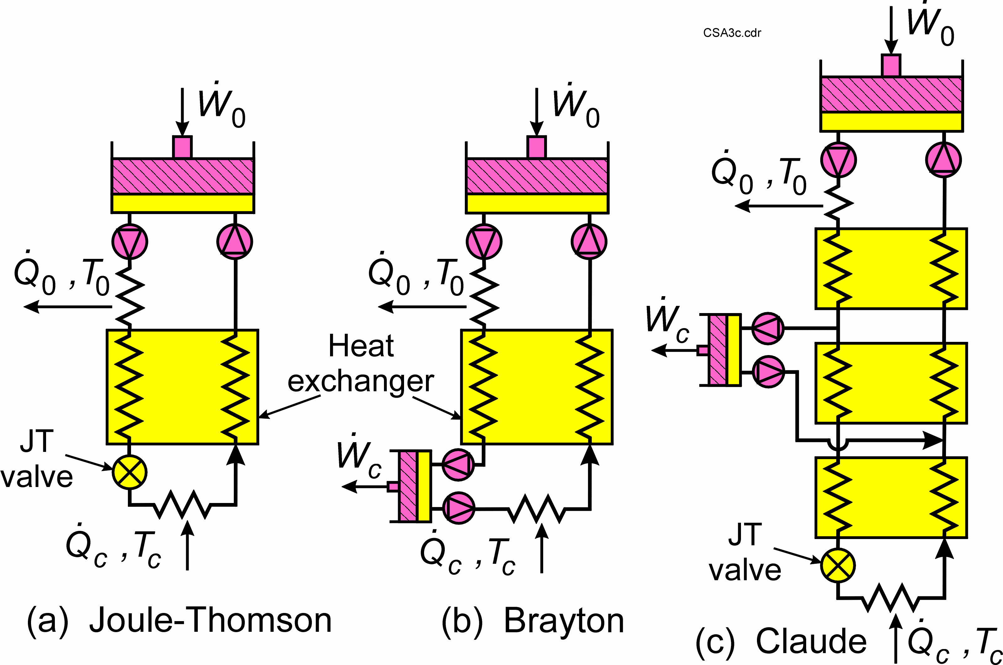
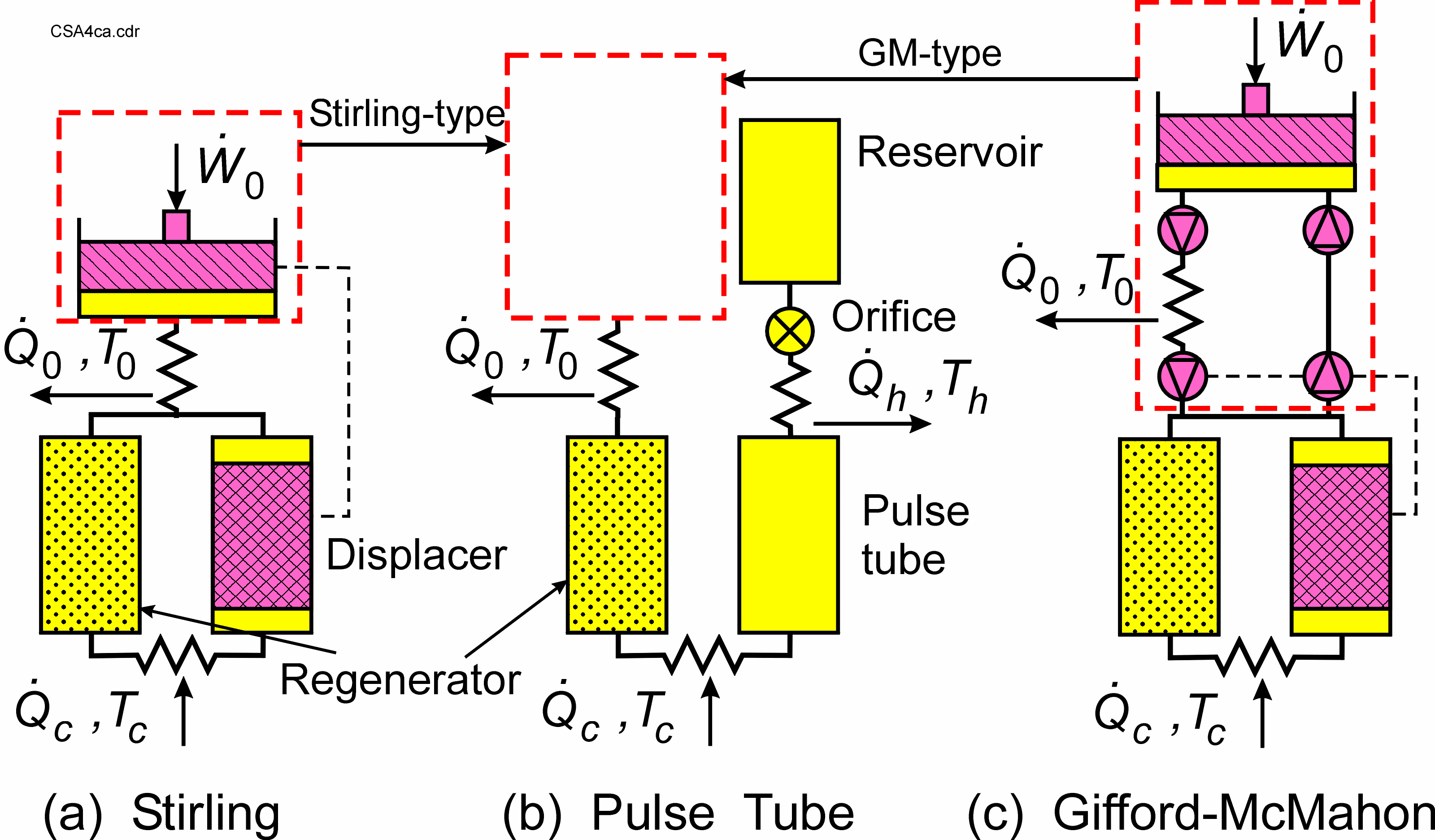
There are commonly used cryocooler types, are classified into two categories — recuperative cycles and regenerative cycles. Schematics of the three most common recuperative cycles are shown in Figure 1. Schematics of the most common regenerative cycles are shown in Figure 2.
Recuperative Cycles
The recuperative cycles move the working fluid around a loop in one direction at fixed high and low pressures. The room-temperature compressor can either be a reciprocating-piston compressor with inlet and outlet valves or a unidirectional compressor without valves, such as a scroll or screw compressor. Efficient oil-removal equipment must be used in the high-pressure stream at room temperature to eliminate all traces of compressor oil from reaching the cold end and freezing. The heat exchanger for the recuperative cycles is known as a recuperator or recuperative heat exchanger. It has two separate flow channels—one for the high-pressure fluid and one for the low-pressure fluid. The low-temperature expansion can be with an orifice, capillary, or valve as in the Joule-Thomson or JT cycle or with an expansion engine as in the Brayton cycle. The Claude cycle is a combination of the two in which an expansion engine is used for precooling and the JT expansion is used for the final expansion. Liquefaction often takes place in the final JT expansion.
The JT cycle normally uses a working fluid that is liquefied at the cold end, such as nitrogen for 77 K, hydrogen for 20 K, and helium for 4.2 K. For higher temperatures, mixed refrigerants of nitrogen and various hydrocarbons are often used to provide higher efficiencies.
Regenerative Cycles
The regenerative cycles, as shown in Figure 2, use oscillating flow and pressure with appropriate phase angles between the flow and pressure to achieve refrigeration at the cold end. Helium gas is almost always used as the working fluid. Maximum refrigeration occurs when flow and pressure are in phase near the cold end. The ideal phase angle is set by the phase of the displacer with respect to the piston in both the Stirling and Gifford-McMahon or GM cycles. The displacer also recovers expansion work at the cold end and re-introduces it at the warm end to reduce the required input power from the compressor or pressure oscillator. Normally, there is no displacer in the pulse tube cryocooler, so the expansion work is lost unless a displacer is used at the warm end of the pulse tube. However, the lack of a displacer greatly reduces vibration at the cold tip. The flow impedance at the warm end of the pulse tube sets the phase between flow and pressure in the pulse tube cryocooler.
The oscillating pressure in regenerative cryocoolers can be generated with a valveless compressor or pressure oscillator, as shown in Figure 2 for the Stirling cycle, or with valves that switch the cold head between a low- and high-pressure source, as shown for the Gifford-McMahon or GM cryocooler. In the latter case, a conventional compressor with inlet and outlet valves or a scroll compressor is used to generate the high- and low-pressure sources. These compressors are commercial oil-lubricated air conditioning or refrigeration compressors modified for use with helium gas, and they are used primarily for commercial applications of cryocoolers where low cost is very important. Oil removal equipment can be placed in the high-pressure line where there is no pressure oscillation. The valves greatly reduce the efficiency of the system, but allow the use of mass-produced refrigeration compressors. Pulse tube cryocoolers can use either source of pressure oscillations, as shown in Figure 2, and they are referred to as either Stirling-type or GM-type depending on the type of compressor used. The Stirling compressors must be oil-free because oil removal equipment cannot be placed in the oscillating pressure region.
The Stirling cycle typically operates with frequencies in the range of 30-60 Hz, whereas the displacer and second set of valves in the Gifford-McMahon cycle operate at 1-2 Hz to achieve longer lifetimes with rubbing parts. Average pressures are often in the range of 1.5-3 MPa or 15-30 bar with oscillating pressure amplitudes of 10-15 % of the average pressure. Stirling-type pulse tube cryocoolers typically operate at 30-60 Hz, whereas the GM-type operate at 1-2 Hz. Average pressures and pressure amplitudes for pulse tube cryocoolers are about the same as those for the Stirling and GM cryocoolers.
The heat exchanger in regenerative cryocoolers is called a regenerative heat exchanger or regenerator. It has only one flow channel in which the flow changes direction every half cycle. The incoming warm stream is precooled during the first half cycle by heat transfer to the regenerator matrix, typically a packed bed of fine screen or packed spheres. The matrix has a high heat capacity to store the heat for a half cycle. During the second half cycle heat is transferred from the matrix to the returning cold stream.
Cold-end temperatures achieved with regenerative cryocoolers vary from about 3 K up to 300 K, though temperatures below 150 K are most common. The lowest temperatures of about 3 K are possible with GM cryocoolers and GM-type pulse tube cryocoolers. The Stirling and Stirling-type pulse tube cryocoolers are mostly used for temperatures above 20 K. They have the highest efficiencies of all cryocoolers, which can be in the range of 10-20 % of Carnot at 80 K.
Working Principle of Mechanical Cryocoolers
Mechanical cryocoolers work on the principle of the Stirling cycle, which involves compressing and expanding a gas to transfer heat from a low-temperature reservoir to a high-temperature heat sink. The Stirling cycle has four stages: compression, heat rejection, expansion, and heat absorption.
During the compression stage, the gas is compressed, and its temperature increases. The gas then flows through a heat exchanger where it releases heat to the environment. During the expansion stage, the gas expands, and its temperature decreases. The gas then flows through another heat exchanger where it absorbs heat from the low-temperature reservoir.
The Stirling cycle is used in several types of mechanical cryocoolers. In a Stirling cryocooler, a piston and cylinder are used to compress and expand the gas. In a Gifford-McMahon cryocooler, a mechanical compressor is used to compress and expand the gas. In a pulse-tube cryocooler, a high-frequency oscillator is used to create pressure waves in the gas, which then drives the compression and expansion.
Joule-Thomson cryocoolers work on a different principle than Stirling cycle-based cryocoolers. These cryocoolers use a throttling valve to expand a gas, which causes it to cool down. The cooled gas is then used to cool the low-temperature reservoir, and the expanded gas is returned to the compressor to be recompressed.
Working Principle of Non-Mechanical Cryocoolers
Non-mechanical cryocoolers use different principles than mechanical cryocoolers to transfer heat from a low-temperature reservoir to a high-temperature heat sink. These cryocoolers are typically more expensive than mechanical cryocoolers, but they are also more reliable and require less maintenance.
Dilution refrigerators use a mixture of helium-3 and helium-4 to transfer heat from a low-temperature reservoir to a high-temperature heat sink. The mixture of helium-3 and helium-4 is cooled by a heat exchanger to a temperature of about 100 mill Kelvin. The mixture is then allowed to separate, with the helium-3 collecting at the bottom of the refrigerator. The helium-3 is then pumped out of the refrigerator, and the process is repeated.
Adiabatic demagnetization refrigerators use the magnetocaloric effect to transfer heat from a low-temperature reservoir to a high-temperature heat sink. These cryocoolers use a strong magnetic field to align the magnetic moments of the atoms in a material. The material is then thermally isolated, and the magnetic field is slowly decreased, which causes the atoms to become disordered and lose their magnetic alignment. This process absorbs heat from the material, which can then be used to cool a low-temperature reservoir.
Applications
There are many common applications of cryocoolers. One of the most common is for the cooling of infrared sensors to temperatures of 80-150 K for use in military night vision equipment. The Stirling or Stirling-type pulse tube cryocoolers are most often used for such applications. Nitrogen or argon JT cryocoolers are used for the rapid cooldown of infrared sensors in missile guidance systems. The superconducting magnet coils in most magnetic resonance imaging or MRI systems are usually kept at 4 K with GM cryocoolers that condense the boil-off from a bath of liquid helium. Many applications of superconducting electronics or power systems utilize the regenerative cryocoolers. Dozens of cryocoolers, mostly Stirling and Stirling-type pulse tube cryocoolers now fly in space aboard satellite for the cooling of infrared sensors. Some have operated continuously for over 10 years. Such cryocoolers use flexure or gas bearings to eliminate rubbing contact in the moving parts.
Details of Closed-cycle refrigerator systems
Where the handling of liquid cryogens is undesirable or when obtaining them is difficult, a mechanical closed-cycle refrigerator can be used. The most common commercially available refrigerators make use of two-stage Gifford-McMahon or G-M or newer pulse tube or PT coolers that use high-purity, 99.999% helium gas as the working fluid.
In these units, the cold head is separated from a compressor by a couple of flexible high-pressure tubes that circulate the compressed helium in and out of the cold head. This enables easy handling of the 8 kg to 15 kg cold head while the heavy compressor, approximately 65 kg to 180 kg, is in a fixed location nearby about 3 meters to 20 meters or 10 to 66 feet. The cold head for the G-M coolers contains displacers or pistons that compress and expand the helium gas inside the two stages of the cold head. It also includes the regenerators having reverse-flow heat exchangers that are critical for cooling the incoming gas, resulting in the ultimate cooling of the second stage. These regenerators are usually made from materials with poor thermal conductivity, high specific heat, and a large surface area to enable them to absorb the heat from the incoming warm helium gas and give up heat to the colder exiting helium gas. The PT coolers have the advantage of not having any displacers or other moving parts, which makes them less likely to require maintenance.
The compressors are typically charged to high pressures of 220 psi to 300 psi. They connect to the cold heads through stainless-steel flexlines and special Aeroquip fittings that allow quick attachment and detachment of the lines without permitting any air into the high-purity helium working gas.
The G-M coolers have inlet and exhaust valves in the cold head that are actuated by a rotary mechanism. The displacers may be driven either pneumatically or by the synchronous motor that drives the valves. The PT coolers with no displacers in the cold head are supplied with a rotary valve and motor that may either be located at the top of the cold head or separated by a semi-flexible line about 60 to 100 cm or 2 to 3.3 feet away. The motor can optionally be electrically isolated from the cold head to reduce the electrical noise to any cryostat attached to the cold head.
The motors must be located in a low magnetic field of 500 Gauss or less not to slow their movement and reduce the cooling power. The cold head itself should also be located in a relatively low magnetic field of 1000 Gauss or less not to risk affecting the performance of the regenerators and reduce the cooling power of these coolers.
The motor and displacer movement frequency in the G-M coolers is about 2 Hz to 3 Hz and varies with the frequency of the available AC signal usually 50 or 60 Hz. The lower frequency of 50 Hz typically results in a lower refrigeration capacity at the first stage but does not affect the cooling capacity at the second stage, except for the 10 K coolers.
In PT coolers, the motor frequency is approximately 1 Hz to 2 Hz, and the cooling power is not affected by the frequency of the AC signal. The motor and associated piston or displacer movement in the G-M cold heads results in a certain level of vibration transmitted to the cold finger and outer body of the cold head. The PT coolers’ lack of moving parts results in fewer vibrations transmitted to the outer body of the cold head, but the cold stages will still have some vibrations associated with the pressure variation during the cooling cycle. These vibrations approximately 4 micro meter are typically lower than the vibrations of a G-M cooler by a factor of 2 to 4. Fortunately, these vibrations are tolerable for many experiments at low temperatures, and special vibration isolation techniques are available to reduce these vibrations to much lower levels. These techniques typically involve using flexible copper braids or an exchange gas mechanism coupled with rigid sample mounting, resulting in less cooling power and higher base temperature at the sample.
In general, the two-stage G-M coolers are available in two categories. The smaller units have a base temperature of 8 K to 10 K with a typical cooling capacity of 2 Watts refrigeration capacity at 20 K, or 2 Watts at 10 K, up to 9 Watts at 20 K or higher. This cooling capacity is satisfactory for most experiments conducted in a typical low-temperature laboratory. The second category of G-M coolers reach temperatures of less than 4.2 K with various cooling powers ranging from 0.1 Watts up to 1.5 Watts at 4.2 K, with base temperatures reaching below 3 K.
These units also require very little maintenance to the cold head or compressor. Typically the compressor filter of activated charcoal adsorber must be replaced after 9,000 to 10,000 hours of use. The filter removes all traces of oil vapors from the helium gas returning to the cold head, and if not replaced could result in some oil vapors contaminating the cold head and freezing there. In some systems, replacement of the displacers and associated gasket seals is also recommended after this period of operation. An elapsed-time meter at the compressor Keeps track of the total operating time.
Two-stage PT coolers are also available in two categories, namely, 10 K and 4.2 K) with the latter in much more demand. The 4.2 K PT coolers are also available in various cooling powers from 0.25 Watts up to 1.5 Watts. The PT cold heads require maintenance every 20,000 hours with potentially even more extended periods up to possibly 30,000 hours, but there is currently not enough data on these relatively new coolers to guarantee that longer maintenance timeframe. One final thing to note is that the PT cold head, unlike the G-M head, cannot operate in an inverted position. The PT cold head can be tipped approximately 15 to 30° from the vertical access before losing some cooling power. The compressor also contains a heat exchanger that dissipates heat generated when the helium gas is compressed. Both water-cooled and air-cooled systems are available, with air-cooled being slightly more expensive. Safety protection switches are installed at the compressor to turn it off if the temperature gets too high. This could happen due to high water temperatures, too low a cooling water throughput, or too high an ambient temperature.
Other protective switches turn the compressor off if the pressure is too high or too low, and a safety pressure relief valve protects against system overcharge. The compressor and cold head must be cleaned using 99.999% pure helium gas, and the system re-charged if it gets contaminated with air, water vapor, or oil or if the pressure drops too low usually below 30 psi. In general, the power requirements for the various refrigerators vary between approximately 2 kW for the 10 K systems up to about 8 kW for the 4 K systems, with AC power input ranging from 220 VAC 1-phase for 10 K systems up to 400 VAC or 470 VAC 3-phase options for the 4 K systems.
The construction of the cold head lends itself naturally to a cryostat with a cold finger configuration. Indeed these refrigerators are also used with appropriate baffles and condensing fin arrays as cryopumps in vacuum chambers requiring clean environments. When used as variable temperature cryostats, two general categories are obtained, with the sample in vacuum or sample in an exchange gas column cooled by the two stages of the refrigerator. These two categories are described in the next sections.
A. Cold finger cryostats
Figure 3 shows the cold head of a 10 K closed-cycle refrigerator with mechanically driven pistons attached to a vacuum jacket and adapter containing electrical feedthroughs, an evacuation valve, and a safety pressure relief valve.
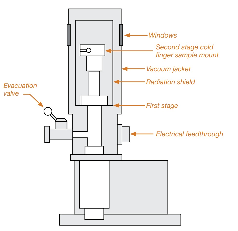
The vacuum jacket surrounds the cold head, consisting of the second refrigerator stage that acts as a cold finger or sample mount and the first stage, which is attached to a radiation shield surrounding the cold finger. This arrangement provides a temperature of 8 K to 10 K at the cold finger, while the radiation shield is cooled to 60 to 80 K by direct contact with the first stage. The Figure 3 shows the cold finger pointing upwards, making it only appropriate for G-M-type coolers because, as mentioned earlier, PT coolers cannot operate in this orientation. A heater attached at the cold finger allows temperature variation up to room temperature. Should higher temperatures be required, a special insulating stage can be added at the second stage.
The insulating stage is needed because the cold head is usually not designed to withstand temperatures much higher than room temperature. In this case, it is advisable to have a protection circuit to prevent the second stage from reaching these higher temperatures and causing damage to the cold head.
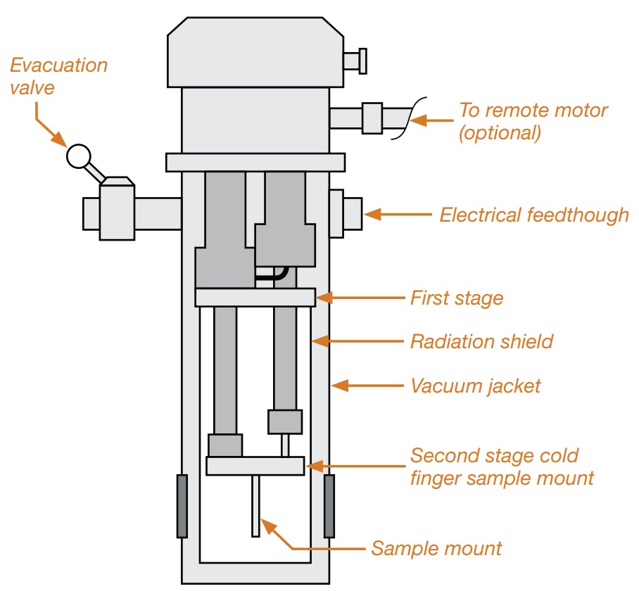
Figure 4 shows a PT cold head in a cold finger configuration where the cold head is oriented upright required for PT coolers. The designs shown in Figures 3 and 4 include a simple arrangement providing optical access to the sample mount. These windows can be eliminated when optical access is not required. The radiation shield and vacuum jacket can be manufactured closer to the cold finger if a more compact configuration is needed. The cold finger can be extended for very tight spaces using a long thin OFHC copper extension to the cold finger. The radiation shield and vacuum jacket can then also be narrowed down to fit inside small spaces such as a pole gap of an electromagnet. The lowest temperature attained at the end of such a sample mount may be one or more degrees higher than the temperature of the cold finger, depending on the details of the setup in question.
A typical system reaches its lowest temperature in about 1 hour. That time is affected by the size of the sample holder and the sample attached to the cold finger. Some units exhibit a small temperature fluctuation of 0.1 to 0.5 K at the lowest achievable cold finger temperatures. The change is related to the displacer motion and associated thermodynamic cooling cycle inside the second stage and can be improved by using an automatic temperature controller and sensor to Keep the temperature slightly higher than the lowest attainable temperature. It can also be minimized or reduced to a few mill Kelvin by adding specially-designed stages to the cold finger.
As with any other cold finger cryostat and the sample in vacuum, it should not be assumed that the sample is exactly at the same temperature as the cold finger. For this purpose, attaching a sensor to the sample can help obtain a more accurate temperature measurement.
B. Exchange gas cryostats
Figure 5 shows the cold head of a 7 K or 10 K G-M closed-cycle refrigerator, with pneumatically driven displacers, attached to an exchange gas sample chamber surrounded by a radiation shield and vacuum jacket. The lower portion of the sample tube is formed from an isothermal copper surface that is cooled by direct contact with the refrigerator’s second stage. The radiation shield is made from aluminum or copper and is cooled by direct contact with the first stage. It surrounds the main length of the sample tube and is anchored to a point at the upper portion of the sample tube to intercept the conductive heat load coming down the sample tube from room temperature.
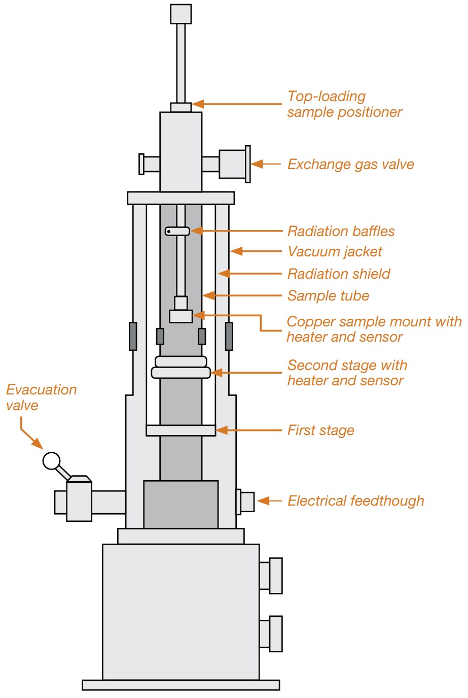
The sample is attached to a copper sample mount supported by a long thin-walled stainless steel tube with baffles, which emerges at the top of the cryostat. Electrical access to the sample area is located at the top of the sample positioner, while electrical access to the second stage inside the vacuum jacket is located near the bottom of the vacuum jacket. Heaters and control sensors may be attached to the second stage of the refrigerator or the sample mount. The temperature may be controlled at either of these two points, with control at the second stage being a little slower because of the large mass attached to that stage. With about half an atmosphere of helium exchange gas in the sample tube, the sample and its holder can be cooled or heated indirectly through the second stage and its heater. Controlling the temperature at the sample mount is quicker because of its smaller mass. Still, it requires good thermal anchoring of the sample to the sample mount to ensure that the sample is at the same temperature as its mount, especially when heated.
The pressure inside the exchange gas tube is not as critical as in the case of a liquid helium Dewar, where helium consumption is a concern. A properly designed system can achieve a temperature of about 10 K at the sample. This arrangement is desirable because it permits quick sample interchange through the top-loading configuration without heating the entire cold head and breaking its vacuum, as required in the cold finger configuration. The exchange pressure must be brought up to atmospheric pressure to prevent air from entering the sample tube while changing samples. The penalty for this arrangement is the higher ultimate temperature about 3 to 5 K higher and added cost of the exchange gas system.
Another advantage of this configuration is that the sample holder can be decoupled from the vibrations generated by the drive mechanism for the displacers and valves inside the cold head. This is done by adding a vibration isolation bellows and a support flange between the sample positioner and the top of the sample tube. The flange can be rigidly bolted to a stationary stage, which supports the sample rod and the bellows. The sample rod and holder, along with the radiation baffles, should make no contact with the walls of the sample tube and should be supported vertically from the stationary stage.
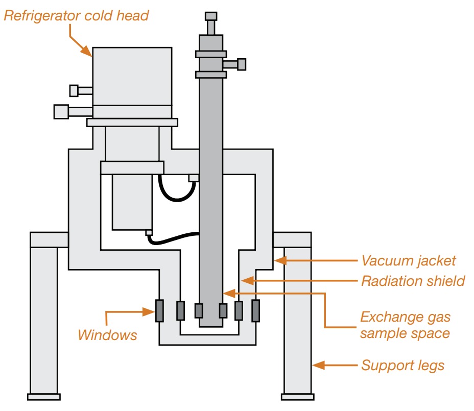
Figure 6 shows another configuration for an exchange gas cryostat that maintains the cold head upright. This geometry can be much more convenient for the end user, albeit a little more expensive to manufacture. In this specific example, a PT-type cold head is used, and the two stages of the cold head are thermally anchored but mechanically decoupled from the exchange gas sample tube where the sample rod is inserted. The decoupling is done with specially designed OFHC copper flexible thermal links having relatively large thermal conductance to ensure the sample reaches a low enough temperature typically 4.5 K or less in a 4 K cooler.
C. Vibration-isolated cryostats
With the increasing interest in cryogen-free systems based on mechanical coolers, there is also the desire to eliminate the vibrations associated with these systems. Two previously mentioned examples locate the sample in an exchange gas environment.
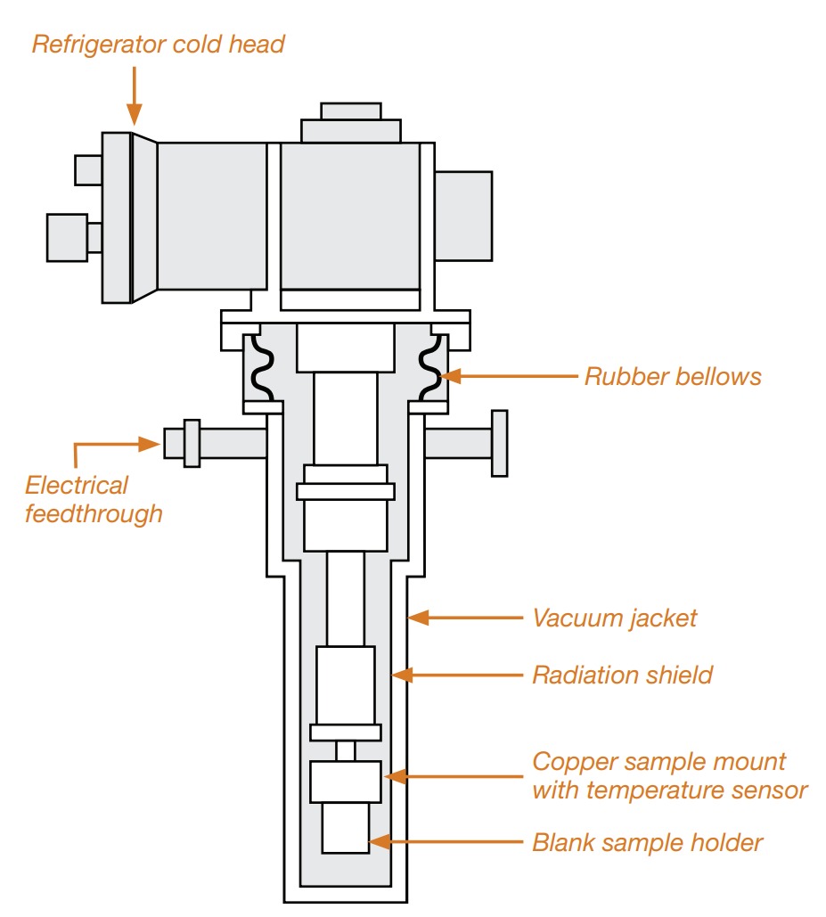
Figure 7 shows an example of such a cryostat with a new cold finger that is mechanically decoupled from the body of the main cold head. In this case, the thermal link to the cold finger and surrounding radiation shield and vacuum jacket is made through helium exchange gas. The cryostat requires rigid support on a vibration-isolated table, and the cold head itself needs to be independently supported. A flexible bellows links the cold head to the cryostat while isolating the cryostat from the vibrations. This design can also be modified into a microscopy-type cryostat where the cold finger is positioned very close to the outer window. The cooling power of the cold head is significantly reduced in these cryostats; the lowest temperature can be several degrees higher than the base temperature of the cold head