Optical Recording
Using light to convey information is as old as signal fires and as natural as sight itself. Over the years, advances in light sources, optical materials, and electronics have radically increased the possibilities for optical information systems. Optics and information go so well together that they're partly responsible for the current information revolution. The introduction of compact disc players in the early 1980s transformed the music industry virtually overnight, and optical fibers are knitting our world together at an astonishing pace.
Representing Sound and Light: Analog and Digital
A CD doesn't store sound any more than a DVD or Blu-ray stores flickering light. Instead, these discs store representations of sound and light that it can use to recreate them on demand. Embedded in each disc is enough information to reproduce a concert or a movie, and to do so almost perfectly. Between the microphones or camera that originally collected that information and the headphones or home theater that finally reconstructs the sound or light are a number of fascinating processes, some optical and some electronic.
A radio wave can be used to represent sound. Sound waves are fluctuations in air's density, and the AM technique represents those density changes by changes in the amplitude of a radio wave. The FM technique is similar, but it represents those density changes by small changes in the frequency of a radio wave. Both techniques are analog representations of the sound, meaning that a continuously variable physical quantity (a radio wave's amplitude or frequency) represents another continuously variable physical quantity (air's density). Like any analog representation, the radio transmitter is drawing an analogy between two continuously variable physical quantities-amplitude or frequency is serving as an analog for air density. The radio receiver draws the reverse analogy and thereby recreates the sound itself.
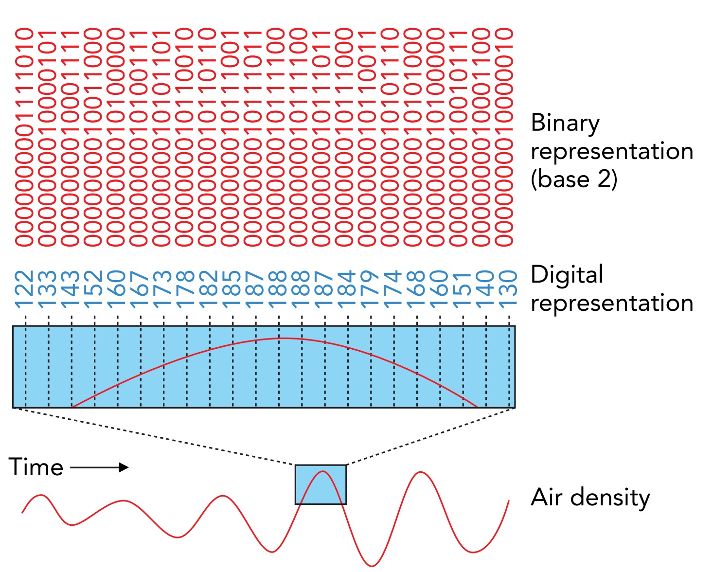
Although parts of the CD player use analog representations for sound, the optical recording and playback part uses a different representation-digital. In digital representations, a continuously variable physical quantity is first represented by a series of numbers and then each of those numbers is represented by a set of physical quantities-a set of digits-each of which can have only a limited number of discrete values. Those discrete values are known as symbols, and symbols can be just about anything, as long as you can tell them apart. As we'll see in a moment, the numerals 0, 1, 2, 3, 4, 5, 6, 7, 8, and 9 are such symbols, and the set of numerals 392 is a digital representation of the number three hundred ninety-two.
Suppose that you're recording your band and want a digital representation of its sound. The first step is to represent that sound's density fluctuations as a series of numbers. With the help of a microphone and some other equipment, you measure the air density many times per second and obtain the series of numbers. Let's assume that one of those numbers is one hundred twenty-four, meaning that the air density during that measurement was 124 units above the normal density.
The second step is to represent each number by a set of digits. We'll allow each digit to hold 1 of 10 possible symbols. Those symbol choices could be , ‚ , , , , , , , and , but let's use a more familiar collection, the numerals 0, 1, 2, 3, 4, 5, 6, 7, 8, and 9. Note that the symbol 5 isn't actually a number; it's just a shape consisting of two straight lines and partial circle.
With a single digit and our set of 10 symbols, we can represent the numbers zero through nine. With 2 digits and those same 10 symbols, we can represent the numbers zero through ninety-nine. With three digits, we can represent zero through nine hundred ninetynine. Since we're trying to represent the number one hundred twenty-four, we clearly need at least three digits. When we place the symbols 1, 2, and 4 in those three digits, as 124, we are representing the number one hundred twenty-four.
The convention that we are following when letting 124 represent one hundred twentyfour is known as decimal. In decimal, we break numbers into ones, tens, hundreds, thousands, and so on-the powers of 10-and use 1 digit and a set of 10 symbols to represent how much of each power of 10 is present in the number we're representing. The decimal representation of one hundred twenty-four is 124, meaning that it contains 1 hundred (10 raised to 2), 2 tens (10 raised to 1), and 4 ones (100). When these pieces are added together, they sum to one hundred twenty-four.
What if, instead of 10 symbols, our collection had only 2 symbols: 0, 1? We could still represent large numbers, but we would need many more digits than before. We would have to break numbers into ones, twos, fours, eights, sixteens, and so on. Instead of using the powers of 10 (as in decimal), we would be using the powers of 2. This system for representing numbers using the powers of 2 is called binary.
In binary, one hundred twenty-four is written as 1111100, meaning that it contains 1 sixty-four (2 raised to 6), 1 thirty-two (2 raised to 5), 1 sixteen (2 raised to 4), 1 eight (2 raised to 3), 1 four (2 raised to 2), 0 twos (2 raised to 1), and 0 ones (2 raised to 0). When these pieces are added together, they again sum to one hundred twentyfour. This apparently complicated way to represent even a fairly small number is actually quite useful. The number has been broken into pieces that have only two possible values; there is either a thirty-two in the number being represented or there isn't.
Binary representations require only two different symbols, and those symbols can be any distinguishable objects. We've been using (1 and 0), but we could use (heads and tails), (smoke and no-smoke), (dot and dash), (shiny and dull), (charged and uncharged), and so on. Inside an optical disc, for example, there is a surface covered with shiny and dull spots, and those spots are a binary representation of numbers. Similarly, in a computer, there are capacitors that are charged or uncharged, and those capacitors are a binary representation of numbers.
There are good reasons for using digital representation to record your band's sound and for using binary. Analog representations are inherently noisy because every accidental change in the physical quantity doing the representing is interpreted as a change in the physical quantity being represented. That's why a phonograph record, which uses height fluctuations in a groove to represent the density fluctuations of sound, can't re-create that sound perfectly. Whenever dust settles into the groove on the record and introduces its own height fluctuations, the phonograph reproduces inaccurate sound, full of pops and snaps.
In contrast, digital representations are noise free. Dust and other imperfections have no effect on digital representations as long as the symbols can still be distinguished for one another. For example, even without brushing the cracker crumbs off your book, laptop, or tablet, you can still read 5049 or 101001 with perfect accuracy, unless you're a total slob. Even when some of the symbols are so badly obscured that they cannot be read, extra symbols can be incorporated into the digital representation to correct for such reading errors.
The reason that binary is so useful in both optical and electronic devices is that working with 2 symbols is much easier than working with 10 of them. The symbols used in these devices aren't shapes on a sheet of paper or computer screen, they're things like the shininess of a surface or the charge on a capacitor. It's easy to distinguish a dull spot (0) from a shiny spot (1) inside an optical disc, but it's much harder to distinguish between dull (0), not quite dull (1), slightly shiny (2), . . . , very shiny (8), and extremely shiny (9) spots. Although there are modern technologies that use more than two symbols, notably digital television transmission, binary is much more common.
Digital Recording
In the conventional CD format, density measurements are made 44,100 times each second for two independent audio channels and these measurements are recorded on the disc in binary form, using 16 bits for each measurement. Since the air density can go down as well as up, these bits represent the positive and negative integers from –32,768 to 32,767, which in turn represent how much the air density is above or below the average density. Density measurements with 16 bits of precision are sufficient to reproduce both loud and soft music with almost perfect fidelity.
Like CDs, DVDs record information digitally. But DVDs are a newer technology and therefore more sophisticated. Audio DVDs can choose from several measurement rates, bits per
measurement, and numbers of channels. A typical DVD might have five audio channels: leftfront, center-front, right-front, left-rear, and right-rear. The three front channels might have 96,000 density measurements per second at 24 bits per measurement, and the two rear channels might have 48,000 measurements per second at 20 bits per measurement. All these samples, bits, and channels involve far more information than is stored on a CD, and a DVD compresses that information before storing it. In contrast, a conventional CD's information is uncompressed although some more modern formats (example, mp3) do employ compression techniques.
In either case, air density measurements aren't simply recorded one after another on a disc's surface. Instead, these numbers are extensively reorganized before they're stored. This reorganization allows the player to reproduce the sound perfectly even if the disc can't be read completely. As we'll see shortly, reading these discs is a technological tour de force and susceptible to various failures. To be sure that the sound (and video) can be reproduced completely and without interruption, the numbers are recorded in an encoded manner. They appear redundantly so that, even if one copy of a number is illegible, there is still enough legible information along the same arc of the disc's spiral track to completely re-create that missing number. This duplication of information reduces the playing time of both CDs and DVDs, but it is essential for reliability.
Its encoding scheme leaves a CD or DVD almost completely immune to all but the most severe playback problems. In principle, you can damage or obscure a 2-mm-wide swath of the disc, from its center to its edge, and the player will still be able to reproduce the sound (and video) perfectly. However, damage along an arc of the spiral track is far more threatening to the data. If the player can't read a long stretch of a single arc, it won't be able to recover the information. That's why you should always clean a CD or DVD from its center outward to its edge.
The Structure of CDs, DVDs, and Blu-rays
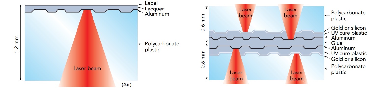
Standard CDs, DVDs, and Blu-rays are 120 mm in diameter and 1.2 mm thick. One side of a CD is clear and smooth but the other side contains a sandwich of layers: a thin film of aluminum, a protective lacquer, and a printed label. In contrast, a DVD is laminated from two 0.6-mm-thick clear plastic discs, with one, two, or four reflective layers of aluminum, gold, or silicon stacked up in between them. The more layers in the DVD, the more information it holds. A Blu-ray disc (BRD) also has 1 to 4 reflective layers, but they are so near the BRD's surface that a hard protective coating is applied to prevent scratches.
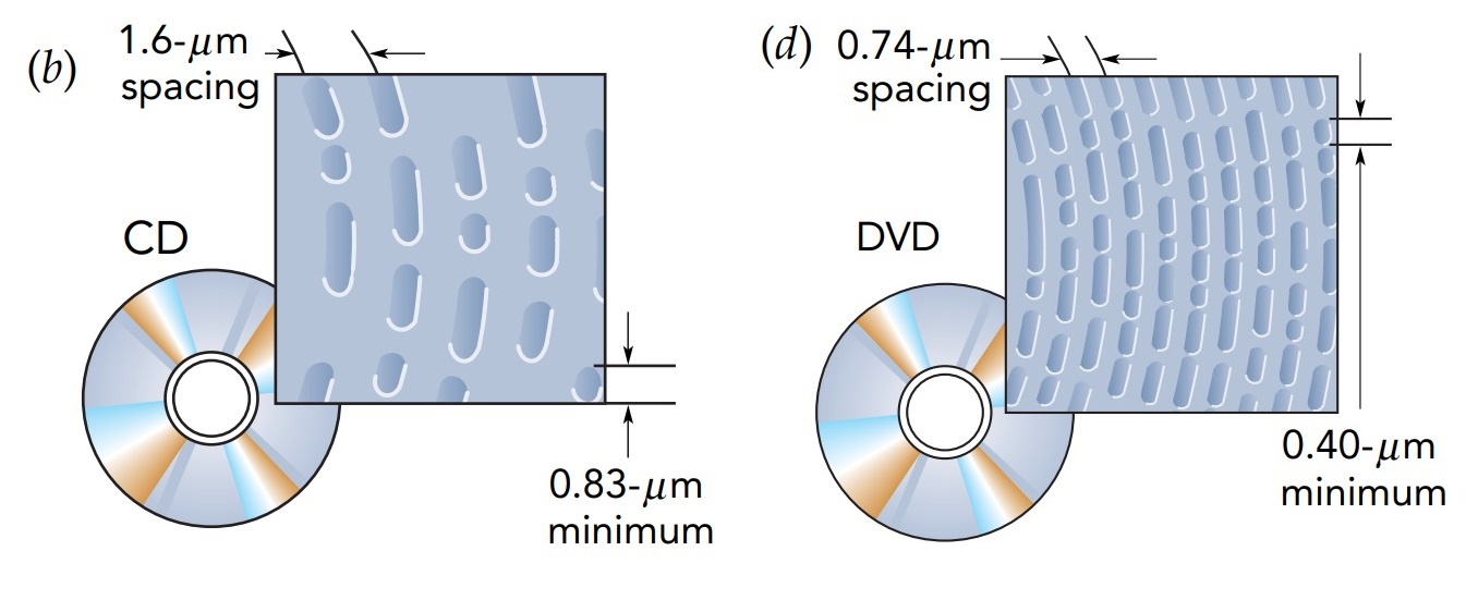
The reflective layers are the recording surfaces. These layers are so thin that they actually transmit a small amount of light. In the gold or silicon DVD layers, this semitransparency is essential because it allows the optical system that reads information to send light through the semitransparent layer to the aluminum layer beyond it. The aluminum layers also transmit some light. Although aluminum's electrons accelerate in response to the light's electric field and normally reflect that light completely, there aren't enough electrons in these 50- to 100-nanometer-thick layers to do the job and some light gets through. The reflective layers aren't perfectly smooth. Instead, each has a narrow spiral track formed in its surface. This track is a series of microscopic pits, as short as 0.83 micro meter long on a CD, 0.40 micro meter long on a DVD, and 0.15 micro meter long on a Blu-ray. Adjacent arcs in the spiral track are only 1.6 micro meter apart on a CD, 0.74 micro meter apart on a DVD, and just 0.32 micro meter apart on a Blu-ray. The lengths of the pits and the flat “lands” that separate them represent numbers. The player examines these pits and lands as the disc turns and converts their lengths into numbers, sound, and video.
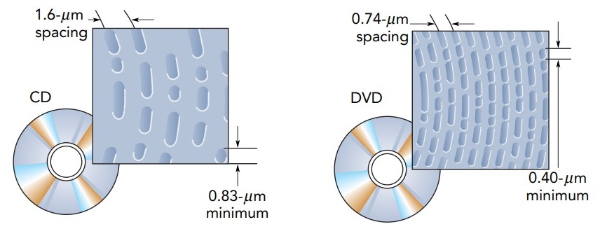
The pit lengths and the spacings between arcs weren't chosen arbitrarily. Since electromagnetic waves are unable to detect structures much smaller than their wavelengths, the laser beam's wavelength limits the size of the smallest features on a disc. In a CD player, that beam's wavelength is 780 nanometer in air and 503 nanometer in polycarbonate plastic-short enough to detect the pits of a CD easily. In a DVD player, the laser beam's wavelength is between 635 and 650 nanometer in air and between 410 and 420 nanometer in plastic-just short enough to detect the pits in a DVD. The wavelength reduction inside the disc occurs because polycarbonate plastic has an index of refraction of 1.55, meaning that the light's speed in that plastic is reduced from its vacuum speed by a factor of 1.55. Its wavelength is reduced by the same factor. In a Blu-ray player, the laser beam's wavelength is 405 nanometer in air and about 260 nanometer in plastic, and it is just able to observe the tiny pits.
The player detects a pit by bouncing light from the disc and determining how much of it reflects. As the focused laser beam passes over a pit, the reflection becomes dim, in part because the curved pit scatters light in all directions and in part because of interference effects. Light that's reflected back from a pit travels farther than light that's reflected from the flat region around it, so electric and magnetic fields in the two waves are shifted relative to one another. The pit depth was chosen so that the two reflected waves are approximately out of phase and they interfere destructively. Overall, the player's light sensors detect relatively little light when the laser beam is located over a pit.
A CD, DVD, or Blu-ray player uses a laser diode to produce its light. The 780-nanometer standard for CD players was adopted in 1980, when 780-nanometer infrared laser diodes were reliable but still fairly expensive. Technology advanced by the mid-1990s, however, and the 635- to 650-nanometer standard for DVD players reflects the development of inexpensive red laser diodes. New standards follow technology, so with the development of reliable blue laser diodes, new optical recording systems appeared. Blu-ray players and discs, which first appeared in 2006, are based on a 405-nanometer laser. Because a Blu-ray player can focus its blue laser beam to a much smaller spot than either a CD or a DVD player, a Blu-ray disc holds far more information than either of the earlier formats.
The Optical System of a CD, DVD, or Blu-ray Player
A CD, DVD, or Blu-ray player's optical system measures the lengths of the tiny pits as they move by on a spinning disc. That reading process requires incredible precision. Not only must the player focus its spot of laser light exactly on the reflective layer, but it must also follow the spiral track as it moves by. The disc itself is neither perfectly flat nor perfectly round, so the player must continuously adjust its reading unit during playback. The optical system must keep its laser beam focused on the reflective layer (autofocusing) and must follow the track as it passes (autotracking). These two automatic processes are beautiful examples of the use of feedback.

The basic structure of a typical CD, DVD, or Blu-ray player. Light from a laser diode passes through several optical elements on its way to the disc's reflective layer. It comes to a tight focus on that layer, where it illuminates only a single he reflected light turns 90° at a special mirror called a polarization beam splitter and focuses on an array of light detectors. The player measures the electric currents flowing through the detectors and uses those measurements both to obtain data from the disc and to control the focusing and tracking systems.
Let's examine this optical system one element at a time. After leaving the laser diode, light passes through a polarization beam splitter. This device analyzes the light's polarization. Different polarizations of light reflect differently when they strike a transparent surface at an angle. In this case, polarized light from the laser passes through the 45° surface, but light of the other polarization reflects. The beam splitter is specially coated to separate the two polarizations almost perfectly.
Light from the laser diode diverges rapidly as it passes through the beam splitter. It's not that the laser diode is broken or poorly designed; it's that a light wave emerging from a small opening naturally spreads outward, like ripples on a pond. This spreading is known as diffraction and occurs whenever a light wave is truncated by passing through an opening. The smaller the opening, the worse is the spreading. Because the emitting surface of the laser diode is essentially a very small opening, the laser beam spreads rapidly as it heads away from the diode. The player uses a converging lens located after the beam splitter to stop this spreading. At that point, the light beam is already wide enough that diffraction causes little additional spreading. The beam leaves the lens collimated, meaning that it maintains a nearly constant diameter after passing through the lens.
The laser light then passes through a quarter-wave plate. This remarkable device performs half the task of converting horizontally polarized light into vertically polarized light or vice versa. Horizontally and vertically polarized lights are said to be plane polarized because their electric fields always oscillate back and forth in one plane as they move through space. The quarter-wave plate turns plane polarized light into circularly polarized light. We encountered circular polarization before in the radio transmissions from FM stations. In circularly polarized light, the electric field actually rotates about the direction in which the light is traveling.
Now the light passes through an objective lens that focuses it onto the reflective layer of the disc. On its way to the reflective layer, the light enters the plastic surface of the disc. At its entry point, the beam is still more than 0.5 mm in diameter, which explains why dust or fingerprints on the disc's surface don't cause much trouble. While contamination may block some of the laser light, most of it continues onward to the reflective layer.
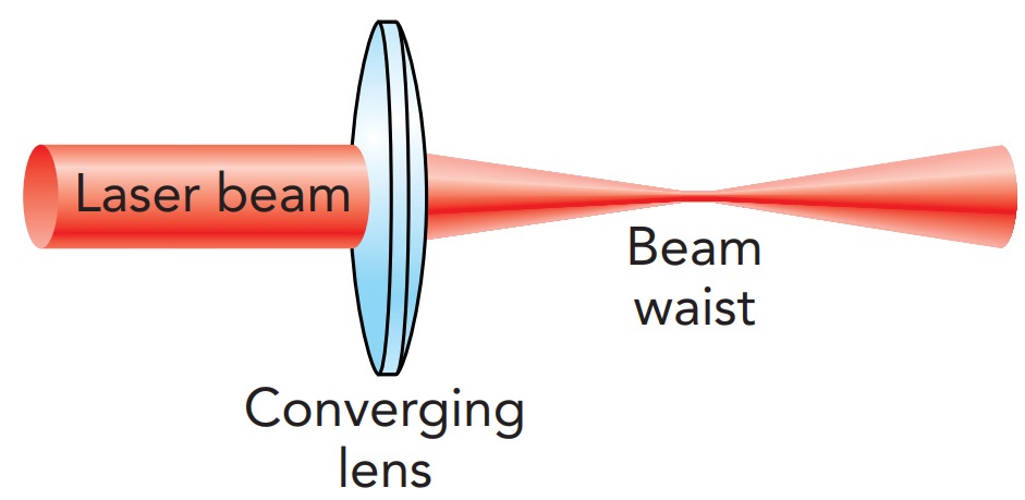
The light comes to a tight focus just as it arrives at the reflective layer. Although it might seem that all the light should converge together to a single point on that surface, it actually forms a spot roughly 1 wavelength in diameter. This spot size is limited by the wave nature of light. No matter how perfectly you try to focus light, you can't make a spot that's much smaller than the light's wavelength. Instead, the beam forms a narrow waist and then spreads apart. This beam waist is about 1 wavelength of the light in diameter and a few wavelengths long, depending on the f-number of the converging lens. Since that waist is less than 2 micro meter long, the player's autofocusing system must keep the objective lens just the right distance from the reflective layer.
This fundamental limitation on how tightly a beam of light can be focused is another example of diffraction; the focusing lens truncates the light wave and inevitably introduces spreading. However, even reaching this ideal focusing limit requires careful design and fabrication of the optical elements. Although most other optical systems fall short of their ideal limits, a CD, DVD, or Blu-ray player's optical system does as well as can be done within the constraints of diffraction itself. Its optics are essentially perfect and are said to be diffraction limited.
The amount of light that reflects from the layer depends on whether or not the laser spot hits a pit. This reflected light follows the optical path in reverse. The light is collimated by the objective lens and then passes through the quarter-wave plate again. The plate now finishes the job it started earlier; the light ends up plane polarized but with the opposite polarization it had when it left the laser. Horizontally polarized light is now vertically polarized, and vice versa.
The reflected light then passes through the collimating lens, which makes the light converge, and then strikes the polarization beam splitter. Because the light's polarization has changed, the beam splitter no longer allows the beam to pass directly through. Instead, it turns this reflected beam 90° and directs it toward the detector array. This clever redirection scheme is important for two reasons. First, it conserves laser light by allowing most of it to travel from the laser diode to the detector. Second, it prevents reflected light from returning to the laser diode, where that light would be amplified and cause the laser diode to misbehave.
The light comes to a focus on an array of photodiodes. This array allows the player to detect pits via the reflected light intensity and also to determine whether the objective lens is properly positioned relative to those pits. The optical elements involved in autofocusing and autotracking is also essential. Because of those elements, the pattern of light hitting the detector array indicates which way the objective lens should move, if necessary. That lens is attached to coils of wire that are suspended near permanent magnets. By varying the currents flowing through those coils, the player uses Lorentz forces to move its objective lens about rapidly and keep it in the right place over the disc.