Audio Players
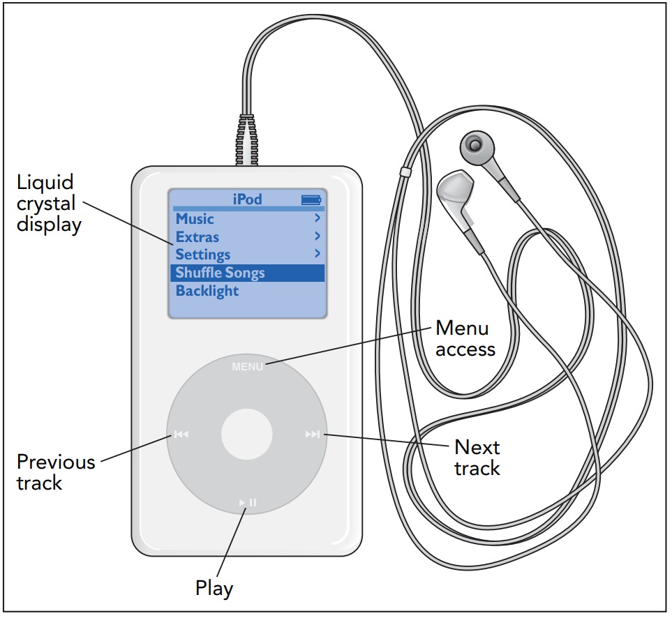
Audio players have revolutionized portable music systems. Everywhere you look, people are sporting earpieces and listening to their favorite tunes with these little electronic marvels or their smartphone siblings. Part computer and part stereo system, an audio player is a spectacular synthesis of some of the highest forms of modern electronic technology. Because they contain such a broad range of electronic components, audio players offer an excellent introduction to much of modern electronics.
To understand how audio players work, we need to look at how sound can be represented electronically and at how those electronic representations can be stored, retrieved, and ultimately used to re-create the sound itself. That exploration will take us all the way from the digital world of computers to the analog world of amplifiers and headphones.
It will also expose us to that workhorse of modern electronics-the transistor. Early audio electronic devices were built with vacuum tubes, which were relatively bulky components that wasted power and aged quickly. Transistors have made audio electronics much more practical. They have also made computers so small and inexpensive that every audio player can have its own computer.
Transistors
The story of audio players begins with the story of transistors. Invented in 1948 by three American physicists, William Shockley (1910–1989), John Bardeen (1908–1991), and Walter Brattain (1902–1987), transistors are key elements in nearly all modern electronic equipment. Like the diodes, transistors are built from doped semiconductors-semiconductors such as silicon to which chemical impurities have been added. However, unlike diodes, which operate in only a single circuit, transistors allow the current in one circuit to control the current in another circuit.
There are many types of transistors, but the simplest and most important type is the field-effect transistor. Actually, even here there are several varieties, so we'll focus on the one that's most widely used in audio players, cell phones, video equipment, and computers: the n-channel metal-oxide-semiconductor field-effect transistor (or n-channel MOSFET). Despite its complicated name, the n-channel MOSFET is a relatively simple device, consisting principally of three semiconductor layers and a nearby metal or metal-like surface. The three layers are called the drain, the channel, and the source, and the metal surface is called the gate.
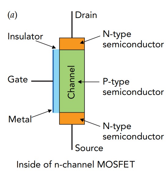
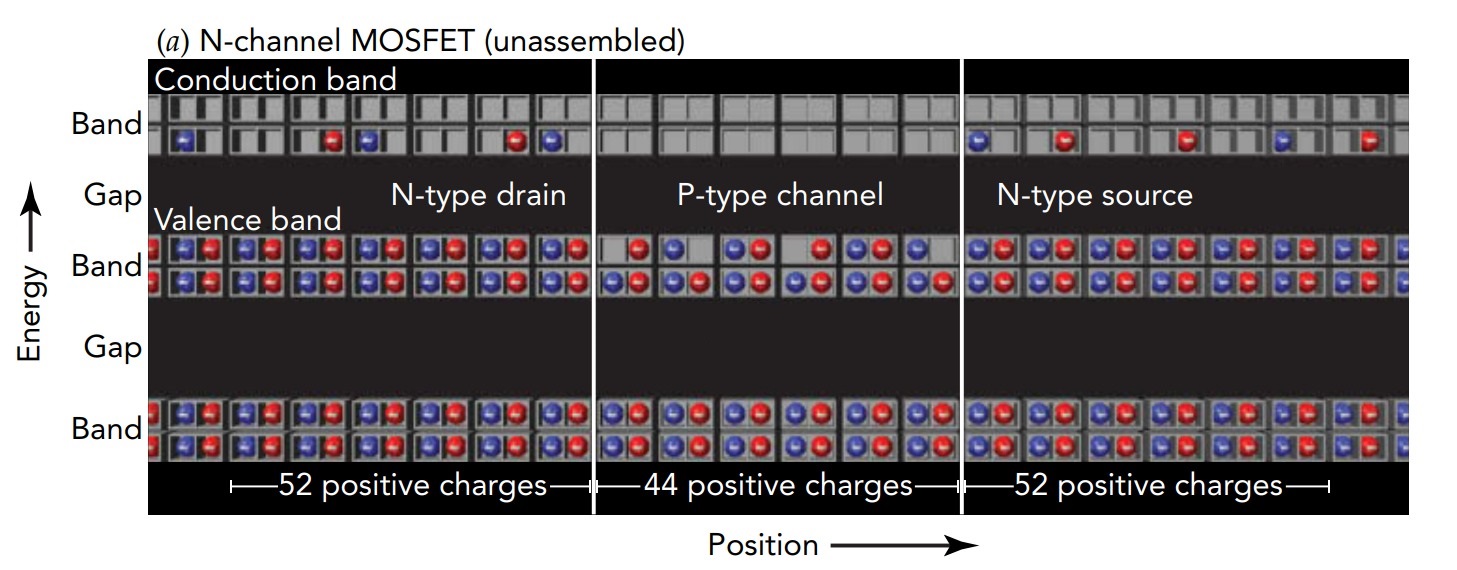
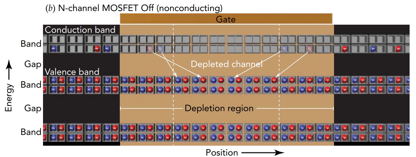
The drain and the source consist of a strongly doped n-type semiconductor (many conduction-level electrons) and the channel between them consists of a lightly doped p-type semiconductor (a few empty valence levels). When those three layers touch, they form two back-to-back p-n junctions, and conduction-level electrons from the drain and source migrate into the channel to fill its few empty valence levels. The completed transistor is thus left with a vast depletion region (a region devoid of empty valence levels or occupied conduction levels) extending all the way from its drain to its source. With nothing to convey charge through its channel, the transistor can't conduct current between its drain and source. The MOSFET is effectively Off.
However, if more electrons could be coaxed into the channel somehow, those electrons would have to go into the channel's conduction levels and the channel would then behave like an n-type semiconductor. With an n-type channel sandwiched between an n-type drain and an n-type source, the p-n junctions would vanish and so would the depletion region. The three layers would become, in effect, a single piece of n-type semiconductor, and the transistor would then be able to conduct current between its drain and source. The MOSFET would be effectively On.
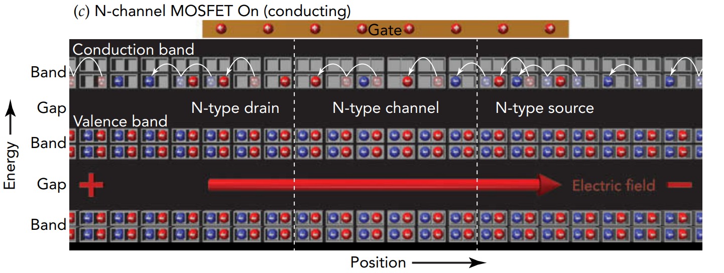
Drawing extra electrons into the channel is the task of the metal-like gate. Separated from the channel by an incredibly thin insulating layer, the gate controls the channel's ability to carry current. When a tiny positive charge is placed on the gate through a wire, it attracts extra electrons into the channel's conduction levels from the source, drain, and their wires and the transistor begins to conduct current. The more positive charge there is on the gate, the more extra electrons are drawn into the channel and the more current can flow through the transistor. In effect, the transistor behaves like an adjustable resistor with a resistance that decreases as the positive charge on its gate increases.
We can now understand the n-channel MOSFET's name. N-channel refers to the channel's n-type behavior when its gate is positively charged and the transistor can carry current. Although the channel is chemically p-type, it becomes electrically n-type when extra electrons are drawn into it and it acquires a negative net charge. Metal-oxide-semiconductor indicates that the metal or metal-like gate is separated from the semiconductor channel by a thin insulating layer of oxide. This insulator can be as little as 1.2 nanometer thick and agonizingly easy to puncture, so modern electronic devices are heavily protected against the damaging effects of static electricity. Field-effect transistor indicates that the electric field from charge on the gate is what draws electrons into the channel and controls the current flow through the transistor.
Storing Digital Sound Information
An audio player is half computer and half stereo system. It stores and manipulates sound information in digital form like a computer but then amplifies that information for the headphones in analog form like a stereo system. We'll mirror that sequence when examining the player's electronics: we'll start with its digital memory and processing systems and finish with its audio amplifier.
Inside the digital portion of the audio player, air pressure measurements and other numbers are represented in binary form. How large or precise those numbers are determines how many binary digits are needed to represent them. Each binary digit is called a bit, and using more bits allows you to represent larger or more precise numbers. In general, the more detailed the information, the more bits are needed to represent it. Eight bits can be used to represent any number from 0 (which is 00000000) to 255 (which is 11111111). Since there are fewer than 256 of many common objects, these objects can be identified by groups of 8 bits. For example, the symbols used in ordinary text have been assigned numbers between 0 and 255, with 65 denoting the letter A. Since the 8 bits 01000001 represent 65, they also specify an A. Groups of 8 bits are so common and useful that they are called bytes.
Although it's possible to store sound information using 1 byte per air pressure measurement, a byte usually doesn't provide enough precision for quality sound reproduction. More often, digital audio is saved using 2 bytes per pressure measurement. These pressure measurements are made tens of thousands of times per second, usually from several microphones simultaneously to provide stereo or surround sound. Even when sophisticated data compression techniques are used to eliminate redundant or inconsequential information, a great many bits are still needed to represent an album. Thus an audio player needs a lot of memory. There are several ways in which the audio player, like any computer, stores a bit. In its main working memory (often called random access memory, or RAM), each bit is a tiny capacitor that uses the presence or absence of separated electric charge to denote a 1 or a 0. The player stores a bit by producing or removing separated charge and recalls the bit by checking for that charge.
Each capacitor is built right at the end of its own n-channel MOSFET. That MOSFET controls the flow of charge to or from the capacitor. To store or recall a bit, the audio player places positive charge on the gate of the MOSFET so that the MOSFET becomes electrically conducting. The memory system can then transfer charge to or from the bit's capacitor. Storing the bit is relatively easy; the player simply sends the appropriate charge through the MOSFET to the capacitor. Recalling the bit is harder because the charge on the capacitor is extremely small. Sensitive amplifiers in the memory system detect any charge flowing through the MOSFET from the capacitor and report what they find to the audio player. Since this reading process removes charge from the capacitor, the memory system must immediately store the bit again.
Unfortunately, these tiny capacitors can't hold separated charge forever because it leaks out to their surroundings. Memory that uses charged capacitors to store bits is called dynamic memory and must be refreshed (read and restored) hundreds of times each second to ensure that a 1 doesn't accidentally switch to a 0 or vice versa. Dynamic memory is also volatile-its contents are lost when the audio player turns off. To conserve its batteries, the player keeps its music information in nonvolatile memory, memory that doesn't need power to retain its information. New possibilities for nonvolatile memory appear almost every year, but at present the three leading forms are flash, magnetic disk, and optical disc memories.
Flash memory resembles dynamic memory in that each bit is stored as the presence or absence of charge associated with a MOSFET. In flash memory, though, that charge resides on the MOSFET's floating gate-a second, unattached gate located in the insulating layer between the channel and the normal gate. Since this floating gate is surrounded by insulator, it can keep its charge for decades. As long as that charge is present, it will determine the MOSFET's conductivity and whether the bit is a 0 or a 1.
Reading bits from flash memory is easy, but storing them is a challenge. The same isolation that traps charge on the floating gate for years makes that charge difficult to change. To add or remove electrons from the floating gate, the memory system applies relatively large voltages to the MOSFET's source, drain, and normal gate and the resulting strong electric fields permit electrons to cross through the insulation separating the channel from the floating gate. To add electrons to the floating gate, the electric fields are arranged so they accelerate channel electrons to such high speeds that those electrons simply burrow right through the insulating layer to the floating gate. To remove electrons from the floating gate, the electric fields are arranged so that the floating gate's electron standing waves are distorted into the insulator. When these distorted waves reach far enough into the insulator, electrons begin to leak through it into the channel via a process known as quantum tunneling.
Flash memory is fast to read but relatively slower to write. Moreover, the electron burrowing process causes cumulative damage to the insulating layer and limits the number of times flash memory can be written. An audio player uses a mixture of dynamic memory and flash memory; it does its computational work in dynamic memory but retains its longterm information in flash memory. However, there's another memory concept that remains more cost-effective than flash memory for storing vast amounts of information-magnetic disk memory. Although flash memory has largely replaced magnetic disks in audio players, computers still depend extensively on magnetic disks.
Just as the magnetic strip on a credit card can store information in the locations of its magnetic poles, the surface of a magnetic disk can store information in the orientations of its magnetic poles. Actual hard disks are smooth aluminum platters that have been coated with hi-tech hard magnetic materials. Using microscopic electromagnets to write magnetic poles and sophisticated semiconductor magnetic sensors to read them, modern hard disks can pack over 1 billion bits into a square millimeter of surface ( or over 80 gigabytes per square inch). Simply locating those microscopic bits on platters that rotate over 100 times per second is an electromechanical tour de force, yet these disks do it routinely even while you are moving your laptop around the room.
The Audio Player's Computer
We've seen how sound information can be represented and stored as bits, so now let's look at how an audio player's computer works with those bits. This digital processing is done by electronic devices that take groups of bits as their inputs and produce new groups of bits as their outputs. Since their output bits are related to their input bits by the rules of logic, these electronic devices are called logic elements.
The simplest logic element is the inverter, which has only one input bit and one output bit. Its output is the inverse of its input. If an inverter's input bit is a 1, then its output bit is a 0, and vice versa. Inverters are used to reverse an action-turning a light on rather than off or starting a song rather than stopping it. Inverters are also used as parts of more complicated logic elements.
But inverters aren't just abstract logic elements; they're real electronic devices. They act on electrical inputs and create electrical outputs. In an audio player's computer, inverters and other logic elements represent input and output bits with electric charge. Positive charge represents a 1, and negative charge represents a 0. Thus when positive charge arrives at the input of an inverter, the inverter releases negative charge from its output. Inverters and other logic elements are usually constructed from both n-channel and p-channel MOSFETs. We've already seen that n-channel MOSFETs conduct current only when their gates are positively charged. P-channel MOSFETs do just the reverse, conducting current only when their gates are negatively charged. The drain and source of a p-channel MOSFET are made from p-type semiconductor, and the channel is made from n-type semiconductor. Since n-channel and p-channel MOSFETs are exact complements to one another, logic elements built from them are called complementary MOSFET or CMOS elements. An audio player's computer is built almost entirely from CMOS elements.
A CMOS inverter consists of one n-channel MOSFET and one p-channel MOSFET. The n-channel MOSFET is connected to the negative terminal of the computer's power supply and controls the flow of negative charge to the inverter's output. The p-channel MOSFET is connected to the power supply's positive terminal and controls the flow of positive charge to the output. When negative charge arrives at the inverter's input and moves onto the gates of the MOSFETs, only the p-channel MOSFET conducts current and the output becomes positively charged. When positive charge arrives at the input, only the n-channel MOSFET conducts current and the output becomes negatively charged.
A computer, however, needs logic elements that are more complicated than inverters. One such element is the Not-AND or NAND gate. This logical element has 2 input bits and 1 output bit, and its output bit is 1 unless both input bits are 1s. It's called a Not-AND gate because it's the inverse of an AND gate. An AND gate produces a 0 output unless both input bits are 1s. Simple memoryless logic elements are often called gates.
A CMOS NAND gate uses two n-channel MOSFETs and two p-channel MOSFETs. The two n-channel MOSFETs are arranged in series-one after the next-so that current passing through one must also pass through the other. If either transistor has negative charge on its gate, no current can flow through the series. Components arranged in series all carry the same current, but they may experience different voltage drops.
The two p-channel MOSFETs are arranged in parallel-one beside the other-so that current can flow through either one of them to the output. If either transistor has negative charge on its gate, current can flow from one side of the pair to the other. Components arranged in parallel share the current they receive through one wire and deliver it together to the second wire. Although parallel components may share the current unevenly among themselves, they all experience the same voltage drop.
If negative charge arrives at either input of the CMOS NAND gate, the series of n-channel MOSFETs will be nonconducting and one of the p-channel MOSFETs will deliver positive charge to the output. However, if positive charge arrives at both inputs, both p-channel MOSFETs will be nonconducting and the series of n-channel MOSFETs will deliver negative charge to the output. Thus the CMOS NAND gate has the correct logic behavior.
These two logic elements, inverters and NAND gates, can be combined to produce any conceivable logic element. For example, they can be used to build an adder, a device that sums the numbers represented by two groups of input bits and produces a group of output bits representing that sum. These adders can themselves be used to build multipliers, and multipliers can be built into still more complicated devices. In this fashion, the simplest logic elements can be used to construct an entire computer.
Actually, a computer isn't built exclusively from NAND gates and inverters. To improve its speed and reduce its size, it uses a few other basic logic elements as well. Like the CMOS NAND gate and inverter, these elements are constructed directly from n-channel and p-channel MOSFETs.
All these logic elements are wired together in an intricate pattern to create a complete computer. In an audio player, this computer retrieves and organizes music information and prepares it for the playback electronics, which are not digital. The computer's last act is to deliver the digital music information, the air pressure measurements, to a digital-to-analog converter, or DAC. This electronic device is the interface between the two representations of information: digital and analog. The music information leaves the DAC as a voltage that's proportional to air pressure. This voltage is the input for the audio player's main analog component, its audio amplifier. Actually, the player has two complete analog audio systems so that it can produce stereo sound. But since those systems are identical, we'll focus on only one of them.
The Audio Player's Audio Amplifier
The fluctuating voltage provided by the audio player's DAC is often called an audio signal because it represents audio information. Many analog or digital representations of information are called signals, including video signals, data signals, and even turn signals. But although the player's audio signal contains all the information needed to reproduce the original sound, in convenient analog format, it doesn't have the power that the headphones need to produce that sound at a reasonable volume. Something must first enlarge the audio signal; it needs to be amplified.
Devices that enlarge various characteristics of signals are called amplifiers. An audio amplifier is an amplifier that's designed to boost signals in the frequency range that we hear or feel (20 to 20,000 Hz). It has two separate circuits-an input circuit and an output circuit-and it uses the small current passing through its input circuit to control a much larger current passing through its output circuit. In this manner, the amplifier provides more power to its output circuit than it receives from its input circuit. Since energy is conserved, an amplifier needs a separate power source to provide its amplification-in this case, the 9-Voltsbattery.
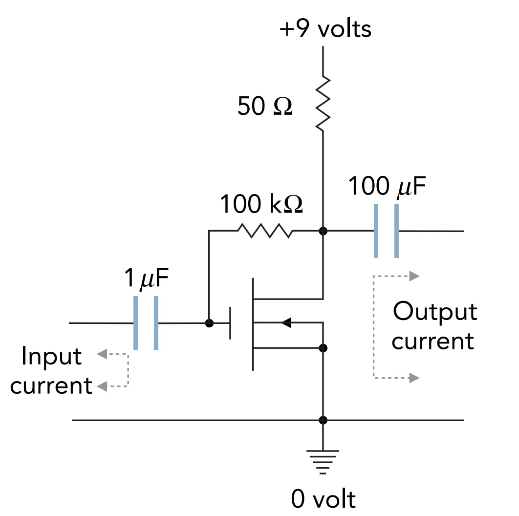
Figure shows the schematic diagram for a simple audio amplifier, built from the components we've just studied. This amplifier has only five components: an n-channel MOSFET, two resistors, and two capacitors. It draws power from a 9-Volt battery (or an equivalent power adapter) and amplifies a tiny alternating current in its input circuit into a large alternating current in its output circuit.
To understand how this amplifier works, let's first remove everything but the MOSFET and the 50-ohm resistor. These two components are in series, so any current that passes through one must also pass through the other. When the MOSFET doesn't conduct current, no current flows through the 50-ohm resistor and it experiences no voltage drop. So the voltage at A is 9 Volts. However, if the transistor does conduct current, a voltage drop will appear through the 50-ohm resistor and the voltage at A will decrease.
The transistor will conduct current only if positive charge is put on its gate. That can be done by connecting the gate to A with a 100-kohm resistor. Since A is at 9 V, it is positively charged and pushes charge toward anything at lower voltage. Current flows slowly through the resistor from A to the gate. However, as positive charge accumulates on the gate, the transistor begins to conduct current and the voltage at A drops. When the voltage at A reaches the voltage on the gate, current stops flowing through the resistor.
The amplifier is then in a stable equilibrium; A has a voltage of approximately 5 Voltsand the transistor's gate has a modest amount of charge on it. The 100-kohm resistor provides the transistor with feedback; that is, it provides the transistor with information about the present situation at A that the transistor can use to correct or improve that situation. Although the feedback is slowed by the resistor's large electrical resistance, it perpetually acts to return the voltage at A to its equilibrium value. If the transistor conducts too little current, charge flows onto its gate and makes it conduct more. If the transistor conducts too much current, charge flows off its gate and makes it conduct less.
The amplifier is now exquisitely sensitive to small changes in the charge on the transistor's gate. If you add just a tiny bit more positive charge to the gate, down goes the voltage at A. If you remove just a tiny bit of positive charge from the gate, up goes the voltage at A. Although current in the feedback resistor tries to undo these changes, it acts too slowly to oppose short-timescale variations. The amplifier's input signal successfully adds or subtracts positive charge from the gate, and the amplifier's output signal emerges from A.
The amplifier has two input wires. An analog audio signal's current flows into the amplifier through one wire and returns through the other. However, the audio signal is not connected directly to the gate. Instead, it's connected to the gate through a capacitor. In addition to storing charge and energy, a capacitor can transfer current between two wires that have different voltages. Such voltage flexibility is important in battery-powered audio amplifiers that must do their amplifying exclusively with positive voltages. Aided by input and output capacitors, our audio amplifier can have an average operating voltage of about +5 Voltswhile it also has average input and output voltages of 0 Volts.
To see how a capacitor passes along current, let's watch input current flow rightward into our amplifier's input capacitor. As that current's positive charge accumulates on the capacitor's left plate, it attracts negative charge onto the capacitor's right plate and away from the gate. The capacitor remains electrically neutral, but the gate becomes more positively charged. Overall, the capacitor has conveyed input current to the gate even though no charge has actually passed through its insulating layer and its two plates remain at different voltages.
With the help of the input capacitor, the amplifier's fluctuating input current produces a fluctuating charge on the transistor's gate, and the voltage at A fluctuates as a result. Even a tiny fluctuating current on the input wires creates a large fluctuating voltage at A.
This fluctuating voltage is responsible for sending a fluctuating current through the headphones. Although headphones are not truly ohmic devices, they respond to fluctuating voltages by carrying fluctuating currents. By applying a fluctuating voltage drop across the headphone's two wires, the amplifier can cause it to carry a fluctuating current and produce corresponding pressure fluctuations and sound.
However, the voltage at A averages about 5 V, while the headphones expect an average voltage drop of 0 Volts. To convey the fluctuating voltages and currents from A to the headphones, while eliminating their large voltage difference, our amplifier connects them via an output capacitor. As before, the fluctuations in current and voltage on the output capacitor's left plate are mirrored by current and voltage fluctuations on its right plate. Even though the amplifier operates at a high average voltage, the output signal for the headphones has an average voltage of 0 Volts.
Tiny fluctuating currents in our amplifier's input circuit produce large fluctuating currents in its output circuit. This amplifier works remarkably well, given its simplicity. If you connect a microphone to the input wires and headphones to the output wires, the headphones will do a surprisingly good job of reproducing the sound in the microphone.
However, our simple amplifier isn't perfect. It distorts the sound somewhat, and it doesn't handle all frequencies or amplitudes of sound equally. It also wastes a large amount of electric power heating the 50-ohm resistor. The amplifiers in audio players carefully correct for these problems. Most use feedback to make sure that their output signals are essentially perfect replicas of their input signals, only larger. They sense their own shortcomings and correct for them.
Perfect replication of the input signal isn't always desirable. Sometimes you want to boost the volume for part of the sound. The treble and bass controls on an audio player allow you to selectively change the loudnesses for the high- and low-frequency portions of the sound, respectively.
An amplifier is typically rated according to the peak power it can supply to the headphones (or speakers) and its average power should never reach that value. Yet the amplifier can reach its peak power during a passage that's not particularly loud. That's because sound waves often interfere with one another, and when their crests and troughs coincide at the microphone, constructive interference can briefly produce enormous pressure fluctuations.
To reproduce those overlapping waves properly, the audio amplifier must be able to provide several times its average power, though only for a moment. If the amplifier can't deliver that much power, the audio signal it sends to the headphones or speakers will be distorted and the sound will be unpleasant. That's why audiophiles often use powerful amplifiers even when they're playing quiet music. Most modern amplifiers are designed cleverly so that they consume only a little more electric power than they actually need to produce their outputs. They consume little power during quiet passages but can still provide great power during the loud moments.
As for the headphones themselves, they generally use electromagnetic effects to move a surface back and forth in sync with the amplifier's current fluctuations. In most cases, the amplifier's current is sent through a coil of wire that's immersed in a strong magnetic field and attached to a movable surface. This current experiences a Lorentz force due to the magnetic field, and that force drives the current, coil, and surface back and forth as the current fluctuates. The moving surface alternately compresses and rarefies the air, thereby reproducing the original sound. The electric power in the circuit becomes sound power for your ears.